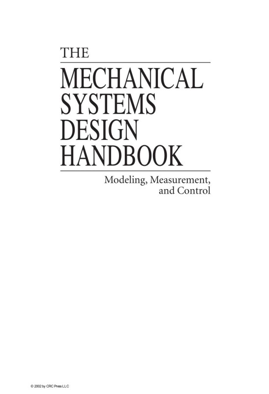
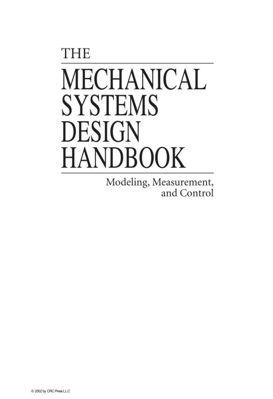
The Mechanical Systems Design Handbook Modeling Measurement and Control 1st Edition by Yildirim Hurmuzlu 1498797784 9781498797788
$50.00 Original price was: $50.00.$25.00Current price is: $25.00.
Authors:OSITA D. I. NWOKAH et al. , Series:Electrical Engineering [80] , Tags:Electricity & Electronics , Author sort:NWOKAH, OSITA D. I. , Languages:Languages:eng , Published:Published:Dec 2002 , Publisher:CRC Press , Comments:Comments:This book contains information obtained from authentic and highly regarded sources. Reprinted material is quoted with permission, and sources are indicated. A wide variety of references are listed. Reasonable efforts have been made to publish reliable data and information, but the authors and the publisher cannot assume responsibility for the validity of all materials or for the consequences of their use. Neither this book nor any part may be reproduced or transmitted in any form or by any means, electronic or mechanical, including photocopying, microfilming, and recording, or by any information storage or retrieval system, without prior permission in writing from the publisher.
The Mechanical Systems Design Handbook Modeling Measurement and Control 1st Edition by Yildirim Hurmuzlu – Ebook PDF Instant Download/Delivery. 1498797784, 9781498797788
Full download The Mechanical Systems Design Handbook Modeling Measurement and Control 1st Edition after payment
Product details:
ISBN 10: 1498797784
ISBN 13: 9781498797788
Author: Yildirim Hurmuzlu
The Mechanical Systems Design Handbook Modeling Measurement and Control 1st Table of contents:
1 Manufacturing Systems and Their Design Principles
1.1 Introduction
1.2 Major Manufacturing Paradigms and Their Objectives
1.3 Significance of Functionality/Capacity Adjustments in Modern Manufacturing Systems
1.4 Critical Role of Computers in Modern Manufacturing
1.5 Design Principles of Modern Manufacturing Systems
1.5.1 Product Design and Design for Manufacturability
1.5.2 Process Planning and System Design of Manufacturing Systems
1.5.3 Software/Hardware Architecture and Communications in Manufacturing Systems
1.5.4 Monitoring and Control of Manufacturing Systems
1.6 Future Trends and Research Directions
2 Computer-Aided Process Planning for Machining
Abstract
2.1 Introduction
2.2 What Is Computer-Aided Process Planning (CAPP)?
2.3 Review of CAPP Systems
2.3.1 Variant Planning
2.3.2 Generative Planning
2.3.3 Hybrid Planning
2.3.4 Artificial Intelligence (AI) Approaches
2.3.5 Object-Oriented Approaches
2.3.6 Part Geometry
2.3.7 Part Specification Input
2.4 Drivers of CAPP System Development
2.4.1 Design Automation
2.4.2 Manufacturing Automation
2.4.3 Extension of Planning Domains; New Planning Domains
2.4.4 Market Conditions
2.4.5 Summary of Drivers
2.5 Characteristics of CAPP Systems
2.6 Integrating CAD with CAPP: Feature Extraction
2.6.1 What Are Features?
2.6.2 Feature Recognition
2.6.2.1 Volume Decomposition
2.6.2.2 Alternating Sums of Volume
2.6.2.3 Graph-Based Recognition
2.6.2.4 Syntactic Pattern Recognition
2.6.2.5 Knowledge-Based Feature Recognition
2.6.2.6 User-Interactive Approaches
2.6.3 Discussion
2.7 Integrating CAPP with Manufacturing
2.7.1 NC Tool-Path Generation
2.7.2 Manufacturing Data and Knowledge
2.8 CAPP for New Domains
2.8.1 Parallel Machining
2.8.1.1 CAPP for Parallel Machining
2.9 Conclusions
3 Discrete Event Control of Manufacturing Systems
3.1 Introduction
3.2 Background on the Logic Control Problems
3.2.1 Logic Control Definition
3.2.2 Control Modes
3.2.3 Logic Control Specification
3.2.4 Tasks of a Logic Control Programmer
3.3 Current Industrial Practice
3.3.1 Programmable Logic Controllers
3.3.2 Relay Ladder Logic
3.3.3 Sequential Function Charts
3.4 Current Trends
3.4.1 Issues with Current Practice
3.4.2 PC-Based Control
3.4.3 Distributed Control
3.4.4 Simulation
3.5 Formal Methods for Logic Control
3.5.1 Important Criteria for Control
3.5.2 Discrete Event Systems
3.5.3 Finite State Machines
3.5.3.1 Combinations of Finite State Machines
3.5.3.2 Supervisory Control of Discrete Event Systems
3.5.3.3 Verification of Closed-Loop Behavior
3.5.4 Petri Nets
3.5.4.1 Graphical Representation of Petri Nets
3.5.4.2 Analysis of Petri Net Models
3.6 Further Reading
4 Machine Tool Dynamics and Vibrations
4.1 Introduction
4.1.1 Mechanical Structure
4.1.2 Drives
4.1.3 Controls
4.2 Chatter Vibrations in Cutting
4.2.1 Stability of Regenerative Chatter Vibrations in Orthogonal Cutting
4.3 Analytical Prediction of Chatter Vibrations in Milling
4.3.1 Dynamic Milling Model
4.3.2 Chatter Stability Lobes
5 Machine Tool Monitoring and Control
5.1 Introduction
5.2 Process Monitoring
5.2.1 Tool Wear Estimation
5.2.2 Tool Breakage Detection
5.2.3 Chatter Detection
5.3 Process Control
5.3.1 Control for Process Regulation
5.3.2 Control for Process Optimization
5.4 Conclusion
6 Process Monitoring and Control of Machining Operations
6.1 Introduction
6.2 Force/Torque/Power Generation
6.2.1 Cutting Force Models
6.2.2 Force/Torque/Power Monitoring
6.2.3 Force/Torque/Power Control
6.3 Forced Vibrations and Regenerative Chatter
6.3.1 Regenerative Chatter Detection
6.3.2 Regenerative Chatter Suppression
6.4 Tool Condition Monitoring and Control
6.4.1 Tool Failure
6.4.2 Tool Wear
6.5 Other Process Phenomena
6.5.1 Burr Formation
6.5.2 Chip Formation
6.5.3 Cutting Temperature Generation
6.6 Future Directions and Efforts
7 Forming Processes: Monitoring and Control
7.1 Introduction: Process and Control Objectives
7.1.1 Process Control Issues
7.1.2 The Process: Material Diagram
7.1.3 The Machine Control Diagram
7.2 The Plant or Load: Forming Physics
7.2.1 Mechanics of Deformation: Machine Load Dynamics
7.2.2 Mechanics of Forming: Bending, Stretching, and Springback
7.2.2.1 Material Variations
7.2.2.2 Machine Variation
7.2.2.3 Material Failure during Forming
7.3 Machine Control
7.3.1 Sensors
7.3.1.1 On Machine
7.3.1.2 On Sheet
7.3.1.3 On Final Part
7.4 Machine Control: Force or Displacement?
7.5 Process Resolution Issues: Limits to Process Control
7.5.1 Process Resolution Enhancement
7.6 Direct Shape Feedback and Control
7.7 Summary
8 Assembly and Welding Processes and Their Monitoring and Control
8.1 Assembly Processes
8.1.1 Monitoring of KPCs
8.1.2 Monitoring of KCCs
8.2 Monitoring and Control of Resistance Welding Process
8.2.1 Monitoring
8.2.2 Control
8.3 Monitoring and Control of Arc Welding Processes
8.3.1 Modeling for Arc Length Control
8.3.2 Weld Bead Geometry Control
8.3.3 Weld Material Properties
8.3.3.1 Bead Size
8.3.3.2 Heat-Affected Zone Size
8.3.3.3 Cooling Rate
8.3.4 Monitoring of Arc Welding and Laser Welding
8.3.4.1 Commercially Available Systems
8.3.4.2 Acoustic Emission
8.3.4.3 Audible Sound
8.3.4.4 Acoustic Nozzle and Acoustic Mirror
8.3.4.5 Infrared/Ultraviolet Sensors
8.3.4.6 Weld Pool Oscillation
8.3.4.7 Optical Sensing
8.3.4.8 Multi-Sensor Systems
8.3.4.9 Seam Tracking
9 Control of Polymer Processing
9.1 Introduction
9.2 Process Description
9.3 Process Variability
9.4 Modeling
9.5 Process Control
9.5.1 Machine Control
9.5.2 State-Variable Control
9.5.3 Set-Point Control
9.6 Conclusions
10 Precision Manufacturing
10.1 Deterministic Theory Applied to Machine Tools
10.2 Basic Definitions
10.3 Motion
10.3.1 Rigid Body Motion and Kinematic Errors
10.3.2 Sensitive Directions
10.3.3 Amplification of Angular Errors, The Abbe Principle
10.3.3.1 Reducing Abbe Error
10.3.3.2 The Bryan Principle
10.4 Sources of Error and Error Budgets
10.4.1 Sources of Errors
10.4.1.1 Geometric Errors
10.4.1.2 Dynamic Errors
10.4.1.3 Workpiece Effects
10.4.1.4 Thermal Errors
10.4.2 Determination and Reduction of Thermal Errors
10.4.3 Developing an Error Budget
10.5 Some Typical Methods of Measuring Errors
10.5.1 Linear Displacement Errors
10.5.2 Spindle Error Motion — Donaldson Reversal
10.5.3 Straightness Errors — Straight Edge Reversal
10.5.4 Angular Motion — Electronic Differential Levels
10.6 Conclusion
10.7 Terminology
11 Active Damping of Large Trusses
Abstract
11.1 Introduction
11.2 Active Struts
11.2.1 Open-Loop Dynamics of an Active Truss
11.2.2 Integral Force Feedback
11.2.3 Modal Damping
11.2.4 Experimental Results
11.3 Active Tendon Control
11.3.1 Active Damping of Cable Structures
11.3.2 Modal Damping
11.3.3 Active Tendon Design
11.3.4 Experimental Results
11.4 Active Damping Generic Interface
11.5 Microvibrations
11.6 Conclusions
12 Semi-Active Suspension Systems
12.1 Introduction
12.1.1 Vibration Isolation vs. Vibration Absorption
12.1.2 Classification of Suspension Systems
12.1.3 Why Semi-Active Suspension?
12.2 Semi-Active Suspensions Design
12.2.1 Introduction
12.2.2 Semi-Active Vibration Absorption Design
12.2.2.1 Harmonic Excitation
12.2.2.2 Broadband Excitation
12.2.2.3 Simulations
12.2.3 Semi-Active Vibration Isolation Design
12.2.3.1 Variable Natural Frequency
12.3 Adjustable Suspension Elements
12.3.1 Introduction
12.3.2 Variable Rate Dampers
12.3.2.1 Electro-Rheological (ER) Fluid Dampers
12.3.2.2 Magneto-Rheological (MR) Fluid Dampers
12.3.3 Variable Rate Spring Elements
12.3.3.1 Variable Rate Stiffness (Direct Methods):
12.3.3.2 Variable Rate Effective Stiffness (Indirect Methods):
12.3.4 Other Variable Rate Elements
12.4 Automotive Semi-Active Suspensions
12.4.1 Introduction
12.3.2 An Overview of Automotive Suspensions
12.4.3 Semi-Active Vehicle Suspension Models
12.4.4 Semi-Active Suspension Performance Characteristics
12.4.5 Recent Advances in Automotive Semi-Active Suspensions
12.5 Application of Control Techniques to Semi-Active Suspensions
12.5.1 Introduction
12.5.2 Semi-Active Control Concept
12.5.3 Optimal Semi-Active Suspension
12.5.4 Other Control Techniques
12.6 Practical Considerations and Related Topics
13 Semi-Active Suspension Systems II
13.1 Concepts of Semi-Active Suspension Systems
13.1.1 Karnopp’s Original Concept
13.1.2 Sky-Hook for Comfort
13.1.3 Extended Ground-Hook for Road-Tire Forces
13.2.4 Semi-Active Actuators and Their Models
13.2 Control Design Methodology
13.2.1 General Design Methodology
13.2.1.1 Design Tools
13.2.1.2 Design Models
13.2.2 Clipped Active Control
13.2.3 MOPO Approach
13.2.4 NQR Approach
13.2.5 Preview Control
13.3 Properties of Semi-Active Suspensions: Performance Indexes
13.3.1 Influence on Comfort
13.3.2 Influence on Road Friendliness
13.4 Examples of Practical Applications
13.4.1 Passenger Cars
13.4.2 Road-Friendly Trucks
13.4.3 Trains
13.4.4 Airplanes
14 Active Vibration Absorption and Delayed Feedback Tuning
14.1 Introduction
14.2 Delayed Resonator Dynamic Absorbers
14.2.1 The Delayed Resonator Dynamic Absorber with Acceleration Feedback
14.2.1.1 Real-Time Tunable Delayed Resonator
14.2.1.2 Vibration Control of Distributed Parameter Structures
14.2.1.3 Stability Analysis of the Combined System
14.2.1.4 Transient Time Analysis
14.2.1.5 Vibration Control of a 3DOF System
14.2.1.6 Vibration Control of a Flexible Beam
14.2.1.7 Summary
14.2.2 Automatic Tuning Algorithm for the Delayed Resonator Absorber
14.2.2.1 Iterative Automatic Tuning Algorithm
14.2.2.2 Tuning to Swept-Frequency Disturbance
14.2.3 The Centrifugal Delayed Resonator Torsional Vibration Absorber
14.2.3.1 Concept of the Centrifugal Delayed Resonator
14.2.3.2 Vibration Control of MDOF Systems Using the CDR
14.2.3.3 Stability of the Combined System
14.2.3.4 Example Implementation
14.2.3.5 Summary
14.3 Multiple Frequency ATVA and Its Stability
14.3.1 Synopsis
14.3.1.2 Stability Analysis; Directional Stability Chart Method
14.3.1.3 Example Case
14.3.2 Optimum ATVA for Wide-Band Applications
14.3.2.1 Synopsis
14.3.2.2 Delayed Feedback Vibration Absorber (DFVA)
14.3.2.3 The Governing Equations
14.3.2.4 Optimum DFVA
14.3.2.5 Stability of the Combined System
14.3.2.6 Optimization Scheme
14.3.2.7 A Case Study
15 Vibration Suppression Utilizing Piezoelectric Networks
15.1 Introduction
15.2 Passive and Semi-Active Piezoelectric Networks for Vibration Absorption and Damping
15.3 Active-Passive Hybrid Piezoelectric Network Treatments for General Modal Damping and Control
15.4 Active-Passive Hybrid Piezoelectric Network Treatments for Narrowband Vibration Suppression
15.5 Nonlinear Issues Related to Active-Passive Hybrid Piezoelectric Networks
15.6 Summary and Conclusions
16 Vibration Reduction via the Boundary Control Method
16.1 Introduction
16.2 Cantilevered Beam
16.2.1 System Model
16.2.2 Model-Based Boundary Control Law
16.2.3 Experimental Trials
16.3 Axially Moving Web
16.3.1 System Model
16.3.2 Model-Based Boundary Control Law
16.3.3 Experimental Trials
16.4 Flexible Link Robot Arm
16.4.1 System Model
16.4.2 Model-Based Boundary Control Law
16.4.3 Experimental Trials
16.5 Summary
17 An Introduction to the Mechanics of Tensegrity Structures
Abstract
17.1 Introduction
17.1.1 The Benefits of Tensegrity
17.1.1.1 Tension Stabilizes
17.1.1.2 Tensegrity Structures are Efficient
17.1.1.3 Tensegrity Structures are Deployable
17.1.1.4 Tensegrity Structures are Easily Tunable
17.1.1.5 Tensegrity Structures Can be More Reliably Modeled
17.1.1.6 Tensegrity Structures Facilitate High Precision Control
17.1.1.7 Tensegrity is a Paradigm that Promotes the Integration of Structure and Control Disciplines
17.1.1.8 Tensegrity Structures are Motivated from Biology
17.1.2 Definitions and Examples
17.1.3 The Analyzed Structures
17.1.4 Main Results on Tensegrity Stiffness
17.1.4.1 Basic Principle 1: Robustness from Pretension
17.1.4.2 Robustness from Pretension Principle for Tensegrity Structures
17.1.4.3 Basic Principle 2: Changing Shape with Small Control Energy
17.1.5 Mass vs. Strength
17.1.5.1 A 2D Beam Composed of Tensegrity Units
17.1.5.2 A 2D Tensegrity Column
17.2 Planar Tensegrity Structures Efficient in Bending
17.2.1 Bending Rigidity of a Single Tensegrity Unit
17.2.1.1 Effective Bending Rigidity with Pretension
17.2.1.2 Bending Rigidity of the Planar Tensegrity for the Rigid Bar Case (K = 0)
17.2.1.3 Effective Bending Rigidity with Slack String (K > 0)
17.2.2 Mass Efficiency of the C2T4 Class 1 Tensegrity in Bending
17.2.3 Global Bending of a Beam Made from C2T4 Units
17.2.3.1 Bucklings Load
17.2.3.2 Buckling of Beam with Many C2T4 Tensegrity Cells
17.2.4 A Class 1 C2T4 Planar Tensegrity in Compression
17.2.4.1 Compressive Stiffness Derivation
17.2.5 Summary
17.3 Planar Class K Tensegrity Structures Efficient in Compression
17.3.1 Compressive Properties of the C4T2 Class 2 Tensegrity
17.3.2 C4T2 Planar Tensegrity in Compression
17.3.2.1 Compressive Stiffness Derivation
17.3.3 Self-Similar Structures of the C4T1 Type
17.3.3.1 Robustness of the C4T1
17.3.3.2 Mass and Tension of String in a C4T11 Structure
17.3.3.3 Total Mass of a C4T11 Structure
17.3.3.4 C4T1i Structures
17.3.3.5 Mass of Bars in a C4T1i Structure
17.3.3.6 Length to Diameter Ratio of Bar in a C4T1i Structure
17.3.3.7 Mass and Tension of Strings in a C4T1i Structure
17.3.3.8 Total Mass of C4T1i Structure
17.3.4 Stiffness of the C4T1i Structure
17.3.4.1 Stiffness Definition
17.3.4.2 The Stiffness Equation of a C4T1i Structure
17.3.4.3 The Rigid Bar Case
17.3.4.4 The Elastic Bar Case
17.3.5 C4T1i Structure with Elastic Bars and Constant Stiffness
17.3.5.1 C4T1i at δ = 0°
17.3.6 Summary
17.4 Statics of a 3-Bar Tensegrity
17.4.1 Classes of Tensegrity
17.4.1.1 3-Bar SVD Class 1 Tensegrity
17.4.1.2 3-Bar SD Class 1 Tensegrity
17.4.1.3 3-Bar SS Class 2 Tensegrity
17.4.2 Existence Conditions for 3-Bar SVD Tensegrity
17.4.3 Load-Deflection Curves and Axial Stiffness as a Function of the Geometrical Parameters
17.4.4 Load-Deflection Curves and Bending Stiffness as a Function of the Geometrical Parameters
17.4.5 Summary of 3-Bar SVD Tensegrity Properties
17.5 Concluding Remarks
17.5.1 Pretension vs. Stiffness Principle
17.5.2 Small Control Energy Principle
17.5.3 Mass vs. Strength
17.5.4 A Challenge for the Future
18 The Dynamics of the Class 1 Shell Tensegrity Structure
Abstract
18.1 Introduction
18.2 Tensegrity Definitions
18.2.1 A Typical Element
18.2.2 Rules of Closure for the Shell Class
18.3 Dynamics of a Two-Rod Element
18.4 Choice of Independent Variables and Coordinate Transformations
18.5 Tendon Forces
18.6 Conclusion
19 Robot Kinematics
19.1 Introduction
19.2 Description of Orientation
19.2.1 Rotation Matrix
19.2.2 Unit Quaternion
19.2.3 Euler Angles
19.3 Direct Kinematics
19.3.1 Homogeneous Transformation
19.3.2 Denavit-Hartenberg Convention
19.3.3 Joint Space and Task Space
19.4 Inverse Kinematics
19.4.1 Closed-Form Solutions
19.5 Differential Kinematics
19.5.1 Geometric Jacobian
19.5.2 Analytical Jacobian
19.5.3 Singularities
19.6 Differential Kinematics Inversion
19.6.1 Pseudoinverse
19.6.2 Redundancy
19.6.3 Damped Least-Squares Inverse
19.6.4 User-Defined Accuracy
19.7 Inverse Kinematics Algorithms
19.7.1 Jacobian Pseudoinverse
19.7.2 Jacobian Transpose
19.7.3 Use of Redundancy
19.7.4 Orientation Errors
19.8 Further Reading
20 Robot Dynamics
20.1 Fundamentals of Robot Dynamic Modeling
20.1.1 Basic Ideas
20.1.2 Robot Geometry
20.1.3 Equations of Dynamics
20.2 Recursive Formulation of Robot Dynamics
20.2.1 Velocities and Accelerations of Robot Links
20.2.2 Elimination of Reactions — Minimization of Dynamic Model Form
20.2.3 Calculation of Direct and Inverse Dynamics
20.3 Complete Model of Robot Dynamics
20.3.1 Dynamic Model of a DC-Driven Robot
20.3.2 Generalized Form of the Dynamic Model
20.4 Some Applications of Computer-Aided Dynamics
20.4.1 Dynamics and Robot Design
20.4.2 Dynamics in On-Line Control
20.5 Extension of Dynamic Modeling — Some Additional Dynamic Effects
20.5.1 Robot Dynamics — Problems and Research
20.5.2 Dynamics of Robot in Constrained Motion
20.5.3 Robot in Contact with Dynamic Environment
20.5.4 Effects of Elastic Transmissions
21 Actuators and Computer-Aided Design of Robots
21.1 Robot Driving Systems
21.1.1 Present State and Prospects
21.1.2 DC Motors: Principles and Mathematics
21.1.3 How to Mount Motors to Robot Arms
21.1.4 Hydraulic Actuators: Principles and Mathematics
21.1.5 Pneumatic Actuators: Principles and Mathematics
21.2 Computer-Aided Design
21.2.1 Robot Manipulator Design Problem
21.2.2 Robot Design Procedure
21.2.3 Design Condition Input
21.2.3.1 Step 1
21.2.4 Fundamental Mechanism Design
21.2.4.1 Step 2
21.2.4.2 Step 3
21.2.4.3 Step 4
21.2.4.4 Step 5
21.2.4.5 Step 6
21.2.5 Inner Mechanism Design
21.2.5.1 Step 7
21.2.5.2 Step 8
21.2.5.3 Step 9
21.2.5.4 Step 10
21.2.5.5 Step 11
21.2.6 Detailed Structure Design
21.2.6.1 Steps 12 and 13
21.2.6.2 Step 14
21.2.6.3 Step 15
21.2.6.4 Step 16
21.2.6.5 Step 17
21.2.7 Design Example
22 Control of Robots
22.1 Introduction
22.2 Hierarchical Control of Robots
22.2.1 Mission Layer
22.2.2 Task Layer
22.2.3 Action Layer
22.3 Control of a Single Joint of the Robot
22.3.1 Model of Actuator and Joint Dynamics
22.3.2 Synthesis of Servosystem
22.3.3 Influence of Variable Moments of Inertia
22.3.4 Influence of Gravity Moment and Friction
22.3.5 Synthesis of the Servosystem for Trajectory Tracking
22.4 Control of Simultaneous Motion of Several Robot Joints
22.4.1 Analysis of the Influence of Dynamic Forces
22.4.2 Dynamic Control of Robots
22.4.3 Inverse Problem Technique
22.4.4 Effects of Payload Variation and the Notion of Adaptive Control
23 Control of Robotic Systems in Contact Tasks
23.1 Introduction
23.2 Contact Tasks
23.3 Classification of Robotized Concepts for Constrained Motion Control
23.4 Model of Robot Performing Contact Tasks
23.5 Passive Compliance Methods
23.5.1 Nonadaptable Compliance Methods
23.5.2 Adaptable Compliance Methods
23.6 Active Compliant Motion Control Methods
23.6.1 Impedance Control
23.6.1.1 Force-Based Impedance Control
23.6.1.2 Position Based Impedance Control
23.6.1.3 Other Impedance Control Approaches
23.6.2 Hybrid Position/Force Control
23.6.2.1 Explicit Force Control
23.6.2.2 Position Based (Implicit) Force Control
23.6.2.3 Other Force Control Approaches
23.6.3 Force/Impedance Control
23.6.4 Position/Force Control of Robots Interacting with Dynamic Environment
23.7 Contact Stability and Transition
23.8 Synthesis of Impedance Control at Higher Control Levels
23.8.1 Compliance C-Frame
23.8.2 Operating Modes
23.8.3 Change of Impedance Gains — Relax Function
23.8.4 Impedance Control Commands
23.8.5 Control Algorithms
23.8.5.1 Grasping
23.8.5.2 Insertion
23.8.6 Implicit Force Control Integration
23.9 Conclusion
24 Intelligent Soft-Computing Techniques in Robotics
24.1 Introduction
24.2 Connectionist Approach in Robotics
24.2.1 Basic Concepts
24.2.2 Connectionist Models with Applications in Robotics
24.2.3 Learning Principles and Rules
24.3 Neural Network Issues in Robotics
24.3.1 Kinematic Robot Learning by Neural Networks
24.3.2 Dynamic Robot Learning at the Executive Control Level
24.3.3 Sensor-Based Robot Learning
24.4 Fuzzy Logic Approach
24.4.1 Introduction
24.4.2 Mathematical Foundations
24.4.2.1 Fuzzy Sets
24.4.2.2 Operations on Fuzzy Sets
24.4.2.3 Fuzzy Relations
24.4.2.4 Fuzzy Logic
24.4.3 Fuzzy Controller
24.4.3.1 Condition Interface
24.4.3.2 Fuzzy Set Definition Base
24.4.3.3 Control Rules
24.4.3.4 Inference Mechanism
24.4.3.5 Action Interface
24.4.4 Direct Applications
24.4.5 Hybridization with Model-Based Control
24.5 Neuro-Fuzzy Approach in Robotics
24.6 Genetic Approach in Robotics
24.7 Conclusion
25 Teleoperation and Telerobotics
25.1 Introduction
25.2 Hand Controllers
25.2.1 Control Handles
25.2.2 Control Input Devices
25.2.3 Universal Force-Reflecting Hand Controller (FRHC)
25.3 FRHC Control System
25.4 ATOP Computer Graphics
25.5 ATOP Control Experiments
25.6 Anthropomorphic Telerobotics
25.7 New Trends in Applications
26 Mobile Robotic Systems
26.1 Introduction
26.2 Fundamental Issues
26.2.1 Definition of a Mobile Robot
26.2.2 Stanford Cart
26.2.3 Intelligent Vehicle for Lunar/Martian Robotic Missions
26.2.4 Mobile Robots — Nonholonomic Systems
26.3 Dynamics of Mobile Robots
26.4 Control of Mobile Robots
27 Humanoid Robots
27.1 Zero-Moment Point — Proper Interpretation
27.1.1 Introduction
27.1.2 The ZMP Notion
27.1.3 The Difference between ZMP and the Center of Pressure (CoP)
27.2 Modeling of Biped Dynamics and Gait Synthesis
27.2.1 Single-Support Phase
27.2.2 Double-Support Phase
27.2.3 Biped Dynamics
27.2.4 Example
27.3 Control Synthesis for Biped Gait
27.3.1 Synthesis of Control with Limited Accelerations
27.3.2 Synthesis of Global Control with Respect to ZMP Position
27.3.3 Example
27.4 Dynamic Stability Analysis of Biped Gait
27.4.1 Modeling of Composite Subsystems
27.4.2 Stability Analysis
27.4.3 Example
27.5 Realization of Anthropomorphic Mechanisms and Humanoid Robots
27.5.1 Active Exoskeletons
27.5.2 Humanoid Robots
27.5.3 Virtual Humanoid Robot Platform
27.5.4 New Application of the ZMP Concept in Human Gait Restoration
27.6 Conclusion
28 Present State and Future Trends in Mechanical Systems Design for Robot Application
28.1 Introduction
28.2 Industrial Robots
28.2.1 Definition and Applications of Industrial Robots
28.2.2 Robot Kinematic Design
28.2.2.1 Cartesian Robots
28.2.2.2 Cylindrical and Spherical Robots
28.2.2.3 SCARA Type Robots
28.2.2.4 Articulated Robots
28.2.2.5 Modular Robots
28.2.2.6 Parallel Robots
28.2.3 Industrial Robot Application
28.2.3.1 Benefits of Robot Automation
28.2.3.2 Robot Workcell Planning and Design
28.2.3.3 Case Study: Automated High-Frequency Sealing in Measuring Instruments
28.3 Service Robots
28.3.1 From Industrial Robots to Service Robots
28.3.2 Examples of Service Robot Systems
28.3.3 Case Study: A Robot System for Automatic Refueling
28.3.3.1 Introduction
28.3.3.2 Systems Design
28.3.3.3 Refueling Robot System Layout
28.3.3.4 Identification and Localization
28.3.3.5 Robot End-Effector
28.3.3.6 Docking Sensors
28.3.3.7 Experiments and Further Developments
People also search for The Mechanical Systems Design Handbook Modeling Measurement and Control 1st:
the design and improvement of mechanical systems and components
what is mechanical system design
what are mechanical systems in a building
the mechanical design process

