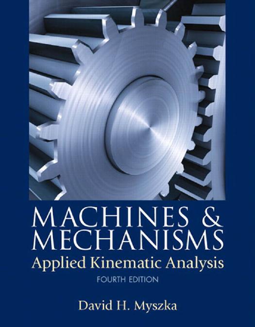
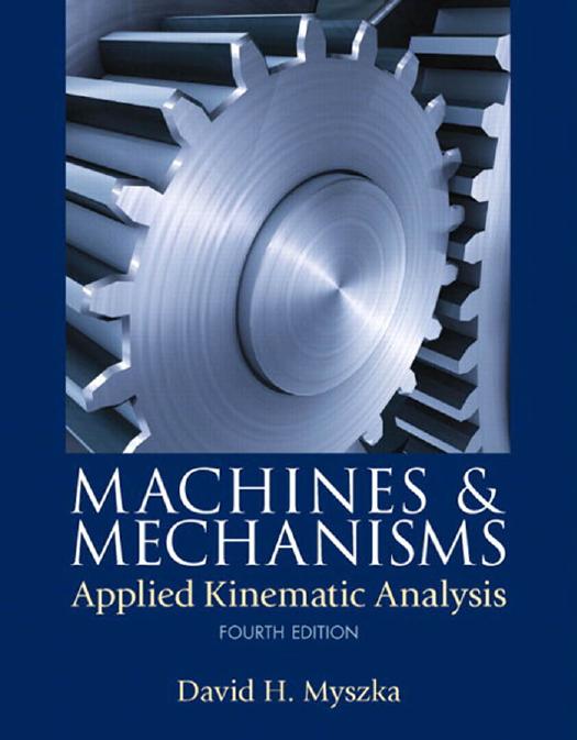
Machines and Mechanisms Applied Kinematic Analysis 4th Edition by David Myszka 0132157802 9780132157803
$50.00 Original price was: $50.00.$25.00Current price is: $25.00.
Authors:David H. Myszka , Series:Mechatronics Engineering [114] , Author sort:Myszka, David H. , Languages:Languages:eng , Published:Published:Feb 2011 , Publisher:Prentice Hall
Machines and Mechanisms Applied Kinematic Analysis 4th Edition by David Myszka – Ebook PDF Instant Download/Delivery. 0132157802, 9780132157803
Full download Machines and Mechanisms Applied Kinematic Analysis 4th Edition after payment
Product details:
ISBN 10: 0132157802
ISBN 13: 9780132157803
Author: David Myszka
This is the eBook of the printed book and may not include any media, website access codes, or print supplements that may come packaged with the bound book. This up-to-date introduction to kinematic analysis ensures relevance by using actual machines and mechanisms throughout. MACHINES & MECHANISMS, 4/e provides the techniques necessary to study the motion of machines while emphasizing the application of kinematic theories to real-world problems. State-of-the-art techniques and tools are utilized, and analytical techniques are presented without complex mathematics. Reflecting instructor and student feedback, this Fourth Edition’s extensive improvements include: a new section introducing special-purpose mechanisms; expanded descriptions of kinematic properties; clearer identification of vector quantities through standard boldface notation; new timing charts; analytical synthesis methods; and more. All end-of-chapter problems have been reviewed, and many new problems have been added.
Machines and Mechanisms Applied Kinematic Analysis 4th Table of contents:
Chapter One Introduction to Mechanisms and Kinematics
Objectives
1.1 Introduction
1.2 Machines and Mechanisms
1.3 Kinematics
1.4 Mechanism Terminology
1.5 Kinematic Diagrams
Solution:
Solution:
1.6 Kinematic Inversion
1.7 Mobility
1.7.1 Gruebler’s Equation
Solution:
Solution:
Solution:
1.7.2 Actuators and Drivers
Solution:
1.8 Commonly Used Links and Joints
1.8.1 Eccentric Crank
1.8.2 Pin-in-a-Slot Joint
1.8.3 Screw Joint
Solution:
1.9 Special Cases of the Mobility Equation
1.9.1 Coincident Joints
Solution:
1.9.2 Exceptions to the Gruebler’s Equation
1.9.3 Idle Degrees of Freedom
1.10 The Four-Bar Mechanism
1.10.1 Grashof’s Criterion
1.10.2 Double Crank
1.10.3 Crank-Rocker
1.10.4 Double Rocker
1.10.5 Change Point Mechanism
1.10.6 Triple Rocker
Solution:
1.11 Slider-Crank Mechanism
1.12 Special Purpose Mechanisms
1.12.1 Straight-Line Mechanisms
1.12.2 Parallelogram Mechanisms
1.12.3 Quick-Return Mechanisms
1.12.4 Scotch Yoke Mechanism
1.13 Techniques of Mechanism Analysis
1.13.1 Traditional Drafting Techniques
1.13.2 CAD Systems
1.13.3 Analytical Techniques
1.13.4 Computer Methods
Problems
Problems in Sketching Kinematic Diagrams
Problems in Calculating Mobility
Problems in Classifying Four-Bar Mechanisms
Chapter Two Building Computer Models of Mechanisms Using Working Model® Software
Objectives
2.1 Introduction
2.2 Computer Simulation of Mechanisms
2.3 Obtaining Working Model Software
2.4 Using Working Model to Model a Four-Bar Mechanism
2.5 Using Working Model To Model a Slider-Crank Mechanism
Problems
Chapter Three Vectors
Objectives
3.1 Introduction
3.2 Scalars and Vectors
3.3 Graphical Vector Analysis
3.4 Drafting Techniques Required in Graphical Vector Analysis
3.5 Cad Knowledge Required in Graphical Vector Analysis
3.6 Trigonometry Required in Analytical Vector Analysis
3.6.1 Right Triangle
Solution:
Solution:
3.6.2 Oblique Triangle
Solution:
Solution:
3.7 Vector Manipulation
3.8 Graphical Vector Addition (+>)
Solution:
Solution:
3.9 Analytical Vector Addition (+>): Triangle Method
Solution:
3.10 Components of A Vector
Solution:
3.11 Analytical Vector Addition (+>): Component Method
Solution:
3.12 Vector Subtraction (−>)
3.13 Graphical Vector Subtraction (−>)
Solution:
Solution:
3.14 Analytical Vector Subtraction (−>): Triangle Method
Solution:
3.15 Analytical Vector Subtraction (−>): Component Method
Solution:
3.16 Vector Equations
Solution:
Solution:
3.17 Application of Vector Equations
3.18 Graphical Determination of Vector Magnitudes
Solution:
3.19 Analytical Determination of Vector Magnitudes
Solution:
Problems
Working with Triangles
Graphical Vector Addition
Analytical Vector Addition
Graphical Vector Subtraction
Analytical Vector Subtraction
General Vector Equations (Graphical)
Solving for Vector Magnitudes (Graphical)
Solving for Vector Magnitudes (Analytical)
Chapter Four Position and Displacement Analysis
Objectives
4.1 Introduction
4.2 Position
4.2.1 Position of a Point
4.2.2 Angular Position of a Link
4.2.3 Position of a Mechanism
4.3 Displacement
4.3.1 Linear Displacement
4.3.2 Angular Displacement
4.4 Displacement Analysis
4.5 Displacement: Graphical Analysis
4.5.1 Displacement of a Single Driving Link
4.5.2 Displacement of the Remaining Slave Links
Solution:
Solution:
4.6 Position: Analytical Analysis
Solution:
4.6.1 Closed-Form Position Analysis Equations for an In-Line Slider-Crank
Solution:
4.6.2 Closed-Form Position Analysis Equations for an Offset Slider-Crank
Solution:
4.6.3 Closed-Form Position Equations for a Four-Bar Linkage
4.6.4 Circuits of a Four-Bar Linkage
4.7 Limiting Positions: Graphical Analysis
Solution:
Solution:
4.8 Limiting Positions: Analytical Analysis
Solution:
4.9 Transmission Angle
4.10 Complete Cycle: Graphical Position Analysis
Solution:
4.11 Complete Cycle: Analytical Position Analysis
Solution:
4.12 Displacement Diagrams
Solution:
4.13 Coupler Curves
Problems
General Displacement
Graphical Displacement Analysis
Analytical Displacement Analysis
Limiting Positions—Graphical
Limiting Positions—Analytical
Displacement Diagrams—Graphical
Displacement Diagrams—Analytical
Displacement Problems Using Working Model
Chapter Five Mechanism Design
Objectives
5.1 Introduction
5.2 Time Ratio
Solution:
5.3 Timing Charts
Solution:
5.4 Design of Slider-Crank Mechanisms
5.4.1 In-Line Slider-Crank Mechanism
5.4.2 Offset Slider-Crank Mechanism
5.5 Design of Crank-Rocker Mechanisms
5.6 Design of Crank-Shaper Mechanisms
5.7 Mechanism to Move a Link Between Two Positions
5.7.1 Two-Position Synthesis with a Pivoting Link
5.7.2 Two-Position Synthesis of the Coupler of a Four-Bar Mechanism
5.8 Mechanism to Move a Link Between Three Positions
5.9 Circuit and Branch Defects
Problems
Time Ratio Calculations
Timing Charts
Design of Slider-Crank Mechanisms
Design of Crank-Rocker Mechanisms
Design of Crank-Shaper Mechanisms
Two-Position Synthesis, Single Pivot
Two-Position Synthesis, Two Pivots
Three-Position Synthesis
Chapter Six Velocity Analysis
Objectives
6.1 Introduction
6.2 Linear Velocity
6.2.1 Linear Velocity of Rectilinear Points
Solution:
6.2.2 Linear Velocity of a General Point
6.2.3 Velocity Profile for Linear Motion
Solution:
6.3 Velocity of a Link
Solution:
6.4 Relationship Between Linear and Angular Velocities
solution:
6.5 Relative Velocity
Solution:
6.6 Graphical Velocity Analysis: Relative Velocity Method
6.6.1 Points on Links Limited to Pure Rotation or Rectilinear Translation
Solution:
6.6.2 General Points on a Floating Link
Solution:
6.6.3 Coincident Points on Different Links
Solution:
6.7 Velocity Image
6.8 Analytical Velocity Analysis: Relative Velocity Method
Solution:
Solution:
6.9 Algebraic Solutions for Common Mechanisms
6.9.1 Slider-Crank Mechanism
6.9.2 Four-Bar Mechanism
6.10 Instantaneous Center of Rotation
6.11 Locating Instant Centers
6.11.1 Primary Centers
Solution:
6.11.2 Kennedy’s Theorem
6.11.3 Instant Center Diagram
Solution:
Solution:
6.12 Graphical Velocity Analysis: Instant Center Method
Solution:
Solution:
6.13 Analytical Velocity Analysis: Instant Center Method
Solution:
6.14 Velocity Curves
Solution:
6.14.1 Graphical Differentiation
Solution:
6.14.2 Numerical Differentiation
solution:
Problems
General Velocity
Relative Velocity
Relative Velocity Method—Graphical
Relative Velocity Method—Analytical
Locating Instantaneous Centers—Graphically
Locating Instantaneous Centers—Analytically
Instantaneous Center Method—Graphical
Instantaneous Center Method—Analytical
Velocity Curves––Graphical
Velocity Curves—Analytical
Velocity Using Working Model
Chapter Seven Acceleration Analysis
Objectives
7.1 Introduction
7.2 Linear Acceleration
7.2.1 Linear Acceleration of Rectilinear Points
7.2.2 Constant Rectilinear Acceleration
Solution:
7.2.3 Acceleration and the Velocity Profile
Solution:
7.2.4 Linear Acceleration of a General Point
7.3 Acceleration of a Link
7.3.1 Angular Acceleration
7.3.2 Constant Angular Acceleration
Solution:
7.4 Normal and Tangential Acceleration
7.4.1 Tangential Acceleration
7.4.2 Normal Acceleration
7.4.3 Total Acceleration
Solution:
7.5 Relative Motion
7.5.1 Relative Acceleration
Solution:
7.5.2 Components of Relative Acceleration
Solution:
7.6 Relative Acceleration Analysis: Graphical Method
Solution:
Solution:
7.7 Relative Acceleration Analysis: Analytical Method
Solution:
7.8 Algebraic Solutions for Common Mechanisms
7.8.1 Slider-Crank Mechanism
7.8.2 Four-Bar Mechanism
7.9 Acceleration of a General Point on a Floating Link
Solution:
7.10 Acceleration image
7.11 Coriolis Acceleration
Solution:
7.12 Equivalent Linkages
7.13 Acceleration Curves
7.13.1 Graphical Differentiation
Solution:
7.13.2 Numerical Differentiation
Solution:
Problems
General Acceleration
Velocity Profiles
Normal and Tangential Acceleration
Relative Acceleration
Relative Acceleration Method—Graphical
Relative Acceleration Method—Analytical
Acceleration of Points on a Floating Link—Graphical
Acceleration of Points on a Floating Link—Analytical
Coriolis Acceleration
Linkage Acceleration with Coriolis—Graphical
Linkage Acceleration with Coriolis—Analytical
Acceleration Curves—Graphical
Acceleration Curves—Graphical
Acceleration Using Working Model
Chapter Eight Computer-Aided Mechanism Analysis
Objectives
8.1 Introduction
8.2 Spreadsheets
Solution:
8.3 User-Written Computer Programs
8.3.1 Offset Slider-Crank Mechanism
8.3.2 Four-Bar Mechanism
Problems
Chapter Nine Cams: Design and Kinematic Analysis
Objectives
9.1 Introduction
9.2 Types of Cams
9.3 Types of Followers
9.3.1 Follower Motion
9.3.2 Follower Position
9.3.3 Follower Shape
9.4 Prescribed Follower Motion
Solution:
9.5 Follower Motion Schemes
9.5.1 Constant Velocity
9.5.2 Constant Acceleration
9.5.3 Harmonic Motion
9.5.4 Cycloidal Motion
Solution:
Solution:
9.5.5 Combined Motion Schemes
Trapezoidal Acceleration
Modified Trapezoidal Acceleration
3 3-4-5 Polynomial Displacement
4 4-5-6-7 Polynomial Displacement
Modified Sinusoidal Acceleration
9.6 Graphical Disk Cam Profile Design
9.6.1 In-Line Knife-Edge Follower
9.6.2 In-Line Roller Follower
9.6.3 Offset Roller Follower
9.6.4 Translating Flat-Faced Follower
9.6.5 Pivoted Roller Follower
9.7 Pressure Angle
9.8 Design Limitations
9.9 Analytical Disk cam Profile Design
9.9.1 Knife-Edge Follower
Solution:
9.9.2 In-Line Roller Follower
Solution:
9.9.3 Offset Roller Follower
9.9.4 Translating Flat-Faced Follower
9.9.5 Pivoted Roller Follower
9.10 Cylindrical Cams
9.10.1 Graphical Cylindrical Cam Profile Design
9.10.2 Analytical Cylindrical Cam Profile Design
9.11 The Geneva Mechanism
Solution:
Problems
Graphical Displacement Diagrams
Analytical Displacement Diagram
Analytical Motion Curves
Graphical Plate Cam Profile Design
Analytical Plate Cam Profile Design
Graphical Cylindrical Cam Design
Analytical Cylindrical Cam Design
Geneva Mechanism Problems
Chapter Ten Gears: Kinematic Analysis and Selection
Objectives
10.1 Introduction
10.2 Types of Gears
10.3 Spur Gear Terminology
10.4 Involute Tooth Profiles
Solution:
10.5 Standard Gears
Solution:
10.6 Relationships of Gears in Mesh
10.6.1 Center Distance
Solution:
10.6.2 Contact Ratio
Solution:
10.6.3 Interference
Solution:
10.6.4 Undercutting
10.6.5 Backlash
Solution:
10.6.6 Operating Pressure Angle
Solution:
10.7 Spur Gear Kinematics
Solution:
10.8 Spur Gear Selection
10.8.1 Diametral Pitch
Solution:
10.8.2 Pressure Angle
10.8.3 Number of Teeth
Solution:
Solution:
Solution:
10.9 Rack and Pinion Kinematics
Solution:
Solution:
10.10 Helical Gear Kinematics
Solution:
10.11 Bevel Gear Kinematics
Solution:
10.12 Worm Gear Kinematics
Solution:
10.13 Gear Trains
Solution:
Solution:
10.14 Idler Gears
10.15 Planetary Gear Trains
10.15.1 Planetary Gear Analysis by Superposition
Solution:
Solution:
10.15.2 Planetary Gear Analysis by Equation
Solution:
Solution:
Problems
Spur Gear Geometry
Gear Kinematics
Gear Selection with an Established Center Distance
Gear Selection with a Set Center Distance
Catalog Gear Selection
Rack and Pinion
Helical Gears
Bevel Gears
Worm Gears
Gear Trains
Gear Train Design
Gear-Driven Mechanisms
Planetary Gear Trains
Chapter Eleven Belt and Chain Drives
Objectives
11.1 Introduction
11.2 Belts
11.3 Belt Drive Geometry
11.4 Belt Drive Kinematics
Solution:
Solution:
11.5 Chains
11.5.1 Types of Chains
11.5.2 Chain Pitch
11.5.3 Multistrand Chains
11.5.4 Sprockets
11.6 Chain Drive Geometry
11.7 Chain Drive Kinematics
Solution:
Problems
Belt Kinematics
Belt Drive Geometry
Belt Drive Selection
Chain Kinematics
Chain Drive Geometry
Chain Drive Selection
Chapter Twelve Screw Mechanisms
Objectives
12.1 Introduction
12.2 Thread Features
12.3 Thread Forms
12.3.1 Unified Threads
12.3.2 Metric Threads
12.3.3 Square Threads
12.3.4 ACME Threads
12.4 Ball Screws
12.5 Lead
12.6 Screw Kinematics
Solution:
Solution:
12.7 Screw Forces and Torques
Solution:
12.8 Differential Screws
Solution:
12.9 Auger Screws
Problems
Screw Thread Geometry
Screw-Driven Displacement
Screw-Driven Velocity
Screw-Driven Acceleration
Screw Force and Torque
Differential Screws
Chapter Thirteen Static Force Analysis
Objectives
13.1 Introduction
13.2 Forces
13.3 Moments and Torques
Solution:
Alternative Solution:
13.4 Laws of Motion
13.5 Free-Body Diagrams
13.5.1 Drawing a Free-Body Diagram
13.5.2 Characterizing Contact Forces
Solution:
13.6 Static Equilibrium
13.7 Analysis of a Two-Force Member
Solution:
Solution:
13.8 Sliding Friction Force
Solution:
Problems
Resultant Force
Moment of a Force
Static Machine Forces
Chapter Fourteen Dynamic Force Analysis
Objectives
14.1 Introduction
14.2 Mass and Weight
14.3 Center of Gravity
Solution:
14.4 Mass Moment of Inertia
14.4.1 Mass Moment of Inertia of Basic Shapes
Solution:
14.4.2 Radius of Gyration
14.4.3 Parallel Axis Theorem
Solution:
14.4.4 Composite Bodies
Solution:
14.4.5 Mass Moment of Inertia—Experimental Determination
14.5 Inertial Force
Solution:
14.6 Inertial Torque
Solution:
Problems
Mass and Mass Moment of Inertia
Inertial Forces
Inertial Torques
People also search for Machines and Mechanisms Applied Kinematic Analysis 4th:
machines & mechanisms applied kinematic analysis 4e
difference between kinematics and mechanics
applications of applied mechanics
theory of machines and mechanisms 4th edition
You may also like…
eBook PDF
Applied Econometrics 4th Edition by Dimitrios Asteriou, Stephen Hall 1352012022 9781352012026

