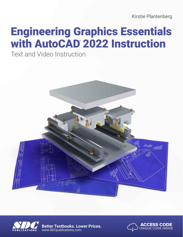
Engineering Graphics Essentials With AutoCAD 2022 Instruction Text and Video Instruction 14th Edition by Kirstie Plantenberg 1630574341 9781630574345
$50.00 Original price was: $50.00.$25.00Current price is: $25.00.
Authors:Kirstie Plantenberg , Series:Mechanical engineering [62] , Tags:Computers; Design; Graphics & Media; Cad-Cam , Author sort:Plantenberg, Kirstie , Ids:9781630574345 , Languages:Languages:eng , Published:Published:Jul 2021 , Publisher:SDC Publications , Comments:Comments:Engineering Graphics Essentials with AutoCAD 2022 Instruction gives students a basic understanding of how to create and read engineering drawings by presenting principles in a logical and easy to understand manner. It covers the main topics of engineering graphics, including tolerancing and fasteners, while also teaching students the fundamentals of AutoCAD 2022. This book features independent learning material containing supplemental content to further reinforce these principles. Through its many different exercises this text is designed to encourage students to interact with the instructor during lectures, and it will give students a superior understanding of engineering graphics and AutoCAD.The independent learning material allows students to go through the topics of the book independently. The main content of the material contains pages that summarize the topics covered in the book. Each page has voice over content that simulates a lecture environment. There are also interactive examples that allow students to go through the instructor led and in-class student exercises found in the book on their own. Video examples are also included to supplement the learning process.Multimedia Content• Summary pages with audio lectures (includes closed captioning)• Interactive exercises and puzzles• Videos demonstrating how to solve selected problems (includes closed captioning)• AutoCAD video tutorials (includes closed captioning)• Supplemental problems and solutions• Tutorial starter files
Engineering Graphics Essentials With AutoCAD 2022 Instruction Text and Video Instruction 14th Edition by Kirstie Plantenberg – Ebook PDF Instant Download/Delivery. 1630574341, 9781630574345
Full download Engineering Graphics Essentials With AutoCAD 2022 Instruction Text and Video Instruction 14th Edition after payment
Product details:
ISBN 10: 1630574341
ISBN 13: 9781630574345
Author: Kirstie Plantenberg
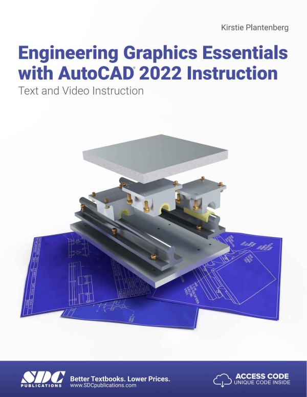
Engineering Graphics Essentials with AutoCAD 2022 Instruction gives students a basic understanding of how to create and read engineering drawings by presenting principles in a logical and easy to understand manner. It covers the main topics of engineering graphics, including tolerancing and fasteners, while also teaching students the fundamentals of AutoCAD 2022. This book features independent learning material containing supplemental content to further reinforce these principles. Through its many different exercises this text is designed to encourage students to interact with the instructor during lectures, and it will give students a superior understanding of engineering graphics and AutoCAD. The independent learning material allows students to go through the topics of the book independently. The main content of the material contains pages that summarize the topics covered in the book. Each page has voice over content that simulates a lecture environment. There are also interactive examples that allow students to go through the instructor led and in-class student exercises found in the book on their own. Video examples are also included to supplement the learning process. Multimedia Content Summary pages with audio lectures (includes closed captioning) Interactive exercises and puzzles Videos demonstrating how to solve selected problems (includes closed captioning) AutoCAD video tutorials (includes closed captioning) Supplemental problems and solutions Tutorial starter files Each chapter contains these types of exercises: Instructor led in-class exercises Students complete these exercises in class using information presented by the instructor using the PowerPoint slides included in the instructor files. In-class student exercises These are exercises that students complete in class using the principles presented in the lecture. Video Exercises These exercises are found in the text and correspond to videos found in the independent learning material. In the videos the author shows how to complete the exercise as well as other possible solutions and common mistakes to avoid. Interactive Exercises These exercises are found in the independent learning material and allow students to test what they’ve learned and instantly see the results. End of chapter problems These problems allow students to apply the principles presented in the book. All exercises are on perforated pages that can be handed in as assignments. Review Questions The review questions are meant to encourage students to recall and consider the content found in the text by having them formulate descriptive answers to these questions. Crossword Puzzles Each chapter features a short crossword puzzle that emphasizes important terms, phrases, concepts, and symbols found in the text.
Engineering Graphics Essentials With AutoCAD 2022 Instruction Text and Video Instruction 14th Table of contents:
Chapter 1: Introduction to Engineering Drawings
1.1) DESIGN
1.2) COMMUNICATING A DESIGN
1.2.1) Sketching
1.2.2) Technical Drawing
1.2.3) Computer-Aided Drawing
1.3) STANDARDS
1.4) HISTORY OF TECHNICAL DRAWING
1.5) MANUFACTURING
1.6) ENGINEERING DRAWING FORMAT AND CONTENTS
1.6.1) Sheet Sizes
1.6.2) Drawing
1.6.3) Zoning
1.6.4) Scale
1.6.5) Notes
1.6.6) Title Block
1.6.7) Revision History Block
1.6.8) Tolerance and Projection Blocks
INTRODUCTION TO ENGINEERING DRAWINGS QUESTIONS
INTRODUCTION TO ENGINEERING DRAWINGS PROBLEMS
Chapter 2: Drawing in AutoCAD
2.1) INTRODUCTION
2.1.1) Navigating through the AutoCAD tutorials
2.2) AUTOCAD’S WORKSPACES AND USER INTERFACE
2.3) THE DRAWING AREA
2.4) ACCESSING AUTOCAD COMMANDS
2.4.1) Application button
2.4.2) The ribbon
2.4.3) Tool palettes
2.4.4) Command prompt / window
2.4.5) Shortcut menus
2.4.6) Application status bar
2.4.7) Quick access toolbar
2.4.8) Touch screen
2.5) STARTING, SAVING, AND OPENING DRAWINGS
2.5.1) Starting a new drawing
2.5.2) Saving and opening a drawing
2.5.3) File tab
2.5.4) Saving and opening from the web or mobile device.
2.6) CUSTOMIZE USER INTERFACE (CUI)
2.7) USER INTERFACE AND STARTUP TUTORIAL
2.7.1) Setting up the user interface
2.7.2) Starting a new drawing
2.7.3) Saving your drawing as a template
2.7.4) Checking your drawing parameters
2.8) COORDINATES
2.8.1) Cartesian and polar coordinates
2.8.2) Cartesian coordinate system
2.8.3) Polar Coordinates
2.8.4) Relative coordinates
2.8.5) World coordinate system (WCS) and user coordinate system (UCS)
2.8.6) The coordinates panel
2.8.7) Coordinate position
2.9) WCS/UCS COORDINATE SYSTEMS TUTORIAL
2.9.1) Coordinates
2.9.2) Change to the user coordinate system (UCS)
2.9.3) Coordinate display and drawing
2.9.4) Drawing using the UCS coordinate system
2.10) DRAWING USING COORDINATES TUTORIAL
2.10.1) Drawing a rectangle using Cartesian coordinates
2.10.2) Drawing using relative polar coordinates
2.10.3) Drawing using both Cartesian and polar coordinates
2.11) PRINTING
2.11.1) Page setup
2.11.2) Plot
2.11.3) Printing to scale
2.12) PRINTING TUTORIAL
2.12.1) Creating the drawing
2.12.2) Printing
2.12.3) Printing to scale
2.12.4) Printing to PDF
2.13) DRAW COMMANDS
2.13.1) Line
2.13.2) Construction line
2.13.3) Ray
2.13.4) Polyline
2.13.5) Polygon
2.13.6) Rectangle
2.13.7) Arc
2.13.8) Circle
2.13.9) Spline
2.13.10) Ellipse
2.13.11) Point
2.14) TEXT
2.14.1) Style
2.14.2) Single-line text
2.14.3) Multi-lined text
2.15) MODIFY COMMANDS
2.15.1) Selecting objects
2.15.2) Erase
2.15.3) Copy
2.15.4) Mirror
2.15.5) Offset
2.15.6) Array
2.15.7) Move
2.15.8) Rotate
2.15.9) Scale
2.15.10) Stretch
2.15.11) Lengthen
2.15.12) Trim
2.15.13) Extend
2.15.14) Break
2.15.15) Join
2.15.16) Chamfer
2.15.17) Fillet
2.15.18) Blend curves
2.15.19) Explode
2.16) OBJECT SNAP COMMANDS
2.16.1) Endpoint
2.16.2) Midpoint
2.16.3) Intersection
2.16.4) Apparent intersection
2.16.5) Extension
2.16.6) Center
2.16.7) Quadrant
2.16.8 ) Tangent
2.16.9) Perpendicular
2.16.10) Parallel
2.16.11) Nearest
2.16.12) Snap from
2.16.13) Insert
2.16.14) Node
2.16.15) Geometric Center
2.16.16) Object snaps settings
2.16.17) Object snap cycling and aperture
2.17) WAGON TUTORIAL
2.17.1) Preparing to draw
2.17.2) Drawing
You will be drawing the following scene.
2.17.3) Using modify commands
2.18) SELECTING OBJECTS
2.19) OBJECT SELECTION TUTORIAL
2.19.1) Selecting objects using the pickbox.
2.19.2) Selecting objects using a window
2.20) OBJECT SNAP TUTORIAL
2.20.1) Drawing using osnaps
2.20.2) Trimming
2.21) POLAR TRACKING
2.22) OBJECT SNAP TRACKING
2.23) TRACKING TUTORIAL
2.23.1) Polar tracking
2.24) DYNAMIC INPUT
2.25) DYNAMIC INPUT TUTORIAL
2.25.1) Dynamic input settings
2.26) GRIP BOXES
2.27) GRIP BOX TUTORIAL
2.27.1) Preparing to draw
2.27.2) Fixing the drawing
2.27.3) Modifying the drawings shape
2.28) PARAMETRIC DRAWING
2.28.1) Geometric constraints
2.28.2) Dimensional constraints
2.29) APPLYING PARAMETRIC CONSTRAINTS TUTORIAL
2.29.1) Applying geometric constraints
2.29.2) Applying dimensional constraints
2.30) AUTOMATIC PARAMETRIC CONSTRAINTS TUTORIAL
DRAWING IN AUTOCAD QUESTIONS
DRAWING IN AUTOCAD PROBLEMS
Chapter 3: Orthographic Projections
3.1) ORTHOGRAPHIC PROJECTION INTRODUCTION
3.1.1) The Six Principal Views
3.2) THE GLASS BOX METHOD
3.3) THE STANDARD VIEWS
3.3.1) The Front View
3.4) LINE TYPES USED IN AN ORTHOGRAPHIC PROJECTION
3.5) RULES FOR LINE CREATION AND USE
3.5.1) Hidden Lines
3.5.2) Center Lines
3.5.3) Phantom Lines
3.5.4) Break Lines
3.5.5) Line Type Precedence
3.6) CREATING AN ORTHOGRAPHIC PROJECTION
3.6.1) Projection Symbol
3.7) APPLYING WHAT WE HAVE LEARNED
READING ORTHOGRAPHIC PROJECTIONS QUESTIONS
CREATING ORTHOGRAPHIC PROJECTIONS QUESTIONS
READING ORTHOGRAPHIC PROJECTIONS PROBLEMS
CREATING ORTHOGRAPHIC PROJECTIONS PROBLEMS
Chapter 4: Creating Orthographic Projections in AutoCAD
4.1) INTRODUCTION
4.2) LAYERS
4.2.1) The Layers panel
4.2.2) Layer properties
4.3) LINE TYPE SCALE
4.4) PROPERTIES
4.4.1) The Properties panel
4.5) PRINTING USING PEN WIDTHS
4.6) CREATING LAYERS TUTORIAL
4.6.1) Setting drawing parameters
4.6.2) Creating layers
4.6.3) Drawing on different layers
4.6.4) Line type scale
4.7) BLOCKING
4.8) MODEL AND LAYOUT SPACE
4.8.1) Model space
4.8.2) Layout space
4.9) CENTERLINES
4.10) TITLE BLOCK TUTORIAL
4.10.1) Blocking a title block
4.10.2) Blocking a metric title block
4.11) ORTHOGRAPHIC PROJECTION TUTORIAL
4.11.1) Draw the front view
4.11.2) Drawing the right side view
4.11.3) Drawing the top view
4.11.4) Drawing centerlines
4.11.5) Printing the layout
4.11.6) Printing a metric drawing
ORTHOGRAPHIC PROJECTIONS IN AUTOCAD QUESTIONS
ORTHOGRAPHIC PROJECTIONS IN AUTOCAD PROBLEMS
Chapter 5: Pictorial Drawings
5.1) PICTORIALS INTRODUCTION
5.2) PICTORIAL TYPES
5.3) AXONOMETRIC PROJECTIONS
5.3.1) Types of axonometric pictorials
5.4) OBLIQUE PROJECTIONS
5.4.1) Types of oblique pictorials
5.5) PERSPECTIVE PROJECTIONS
5.5.1) Types of perspective projections
5.6) VISUALIZATION
5.7) DRAWING ISOMETRIC PICTORIALS
5.7.1) Drawing linear features in an isometric pictorial
5.7.2) Drawing circles and radii in an isometric pictorial
5.7.3) Drawing cylinders in an isometric pictorial
5.8) DRAWING CABINET OBLIQUE PICTORIALS
5.8.1) Drawing features of a cabinet oblique pictorial
5.9) APPLYING WHAT WE HAVE LEARNED
READING PICTORIAL DRAWINGS QUESTIONS
CREATING PICTORIAL DRAWINGS QUESTIONS
Reading PICTORIAL DRAWINGS PROBLEMS
Creating PICTORIAL DRAWINGS PROBLEMS
Chapter 6: Creating Pictorial Drawings in AutoCAD
6.1) ISOMETRIC SNAP
6.2) ISOCIRCLES
6.3) ISOMETRIC PICTORIAL TUTORIAL
6.3.1) Setting up to draw an isometric pictorial
6.3.2) Drawing the isometric pictorial
6.4) ISOCIRCLE TUTORIAL
6.4.1) Setting up to draw an isometric pictorial
6.4.2) Drawing the isometric pictorial
CREATING PICTORIALS IN AUTOCAD QUESTIONS
CREATING PICTORIALS IN AUTOCAD PROBLEMS
Chapter 7: Dimensioning
7.1) DETAILED DRAWINGS
7.2) LEARNING TO DIMENSION
7.3) DIMENSION APPEARANCE
7.3.1) Lines Used in Dimensioning
7.3.2) Types of Dimensions
7.3.3) Arrowheads, lettering, and symbols
7.4) FEATURE DIMENSIONS
7.4.1) Drawing Notes
7.5) DIMENSIONING RULES
7.5.1) Dimension placement, spacing and readability
7.5.2) Over/Under dimensioned parts
7.5.3) Manufacturing
7.5.4) Functional dimensioning
7.5.5) Tolerancing
7.6) APPLYING WHAT WE HAVE LEARNED
Name: _________________________________ Date: _______________
Dimension the following object using proper dimensioning techniques.
/
READING DIMENSIONS QUESTIONS
CREATING DIMENSIONS QUESTIONS
READING DIMENSIONS PROBLEMS
CREATING DIMENSIONS PROBLEMS
Chapter 8: Dimensioning in AutoCAD
8.1) INTRODUCTION
8.2) DIMENSION COMMANDS
8.2.1) Dimensions panel
8.2.2) The Leaders panel
8.3) DIMENSION STYLES
8.3.1) Dimension Style Manager
8.3.2) Multileader Style Manager
8.4) DIMENSION VARIABLES
8.4.1) Dimension scale
8.4.2) Dimension and extension lines
8.4.3) Dimension text
8.4.4) Diameter and radial dimensions
8.4.5) Angular dimensions
8.4.6) Alternative units
8.4.7) Toleranced dimensions
8.4.8) Miscellaneous
8.5) ASSOCIATIVE DIMENSIONS
8.6) ANNOTATIVE OBJECTS
8.6.1) Annotative object scale
8.7) DIMENSIONING TUTORIAL
8.7.1) Drawing the object
8.7.2) Drawing linear dimensions
8.7.3) Drawing diameter, radius, and angular dimensions
8.7.4) Drawing leaders
8.7.5) Creating a new dimension style
8.7.6) Annotative objects
8.7.7) Dimension scale and associativity
8.8) EDITING DIMENSION TEXT TUTORIAL
DIMENSIONING IN AUTOCAD QUESTIONS
DIMENSIONING IN AUTOCAD PROBLEMS
Chapter 9: Sectioning
9.1) SECTIONAL VIEWS
9.1.1) Creating a section view
9.1.2) Lines used in sectional views
9.1.3) Rules of sectioning
9.2) BASIC SECTIONS
9.2.1) Full section
9.2.2) Half section
9.2.3) Offset section
9.3) ADVANCED SECTIONS
9.3.1) Aligned section
9.3.2) Rib and web sections
9.3.3) Broken section
9.3.4) Removed section
9.3.5) Revolved section
9.3.6) Non-sectioned parts
9.3.7) Thin sections
9.4) APPLYING WHAT WE HAVE LEARNED
READING SECTION VIEWS QUESTIONS
CREATING SECTION VIEWS QUESTIONS
READING SECTION VIEW PROBLEMS
CREATING SECTION VIEW PROBLEMS
Chapter 10: Creating Section Views in AutoCAD
10.1) INTRODUCTION
10.2) CUTTING PLANE LINES
10.3) HATCHES
10.4) CREATING HATCHES TUTORIAL
10.4.1) Creating hatches
10.4.2) Changing hatch properties
10.5) HALF SECTION TUTORIAL
10.5.1) Inserting the cutting plane line
10.5.2) Creating the half section view
SECTION VIEWS IN AUTOCAD QUESTIONS
SECTION VIEWS IN AUTOCAD PROBLEMS
Chapter 11: Advanced Drawing Techniques
11.1) ADVANCED VIEW TECHNIQUES
11.1.1) Removed and revolved orthographic views
11.1.2) Detail views
11.1.3) Partial views
11.1.4) Auxiliary views
11.1.5) Related parts
11.2) ADVANCED PART TECHNIQUES
11.2.1) Cast and molded parts
11.2.2) Welded parts
ADVANCED DRAWING TECHNIQUES QUESTIONS
ADVANCED DRAWING TECHNIQUES PROBLEMS
Chapter 12: Creating Advanced Drawings in AutoCAD
12.1) INTRODUCTION
12.2) REMOVED AND REVOLVED ORTHOGRAPHIC VIEWS
12.3) DETAIL AND PARTIAL VIEWS
12.4) AUXILIARY VIEW TUTORIAL
12.4.1) Drawing the orthographic projection
12.4.2) Creating the auxiliary view
12.5) SURFACE TEXTURE TUTORIAL
ADVANCED DRAWINGS IN AUTOCAD PROBLEMS
Chapter 13: Tolerancing
13.1) TOLERANCING AND INTERCHANGEABILITY
13.2) TOLERANCING STANDARDS
13.3) TOLERANCE TYPES
13.4) SHAFT-HOLE ASSEMBLY
13.5) INCH TOLERANCES
13.5.1) Types of fits
13.5.2) ANSI standard limits and fits (English)
Shaft
Min. Clear > 0
Determine the basic size and type of fit given the limits for the shaft and hole.
Shaft
13.6) METRIC TOLERANCES
13.6.1) ANSI standard limits and fits (Metric)
13.6.2) Tolerance designation
13.6.3) Basic hole and basic shaft systems
Basic hole system: The basic hole system is used when you want the basic size to be attached to
Basic shaft system: The basic shaft system is used when you want the basic size to be attached
Description
Identify the type of fit and the system used to determine the limits of the following shaft and hole
Fit
13.7) SELECTING TOLERANCES
IT Grades
Shaft
Shaft
Shaft
Shaft
13.8) TOLERANCE ACCUMULATION
13.9) FORMATTING TOLERANCES
13.9.1) Metric tolerances
13.9.2) Inch tolerances
13.9.3) Angular tolerances
13.10) APPLYING WHAT WE HAVE LEARNED
TOLERANCING QUESTIONS
READING TOLERANCES PROBLEMS
CREATING TOLERANCES PROBLEMS
Chapter 14: Tolerancing in AutoCAD
14.1) INTRODUCTION
14.2) TOLERANCE PARAMETERS
14.3) TOLERANCING TUTORIAL
14.3.1) Drawing the object
14.3.2) Tolerancing
TOLERANCING IN AUTOCAD QUESTIONS
TOLERANCING IN AUTOCAD PROBLEMS
Chapter 15: Threads and Fasteners
15.1) FASTENERS
15.2) SCREW THREAD DEFINITIONS
15.3) TYPES OF THREAD
Thread Name
15.4) MANUFACTURING SCREW THREADS
15.5) DRAWING SCREW THREADS
15.5.1) Detailed representation
15.5.2) Schematic representation
15.5.3) Simplified representation
15.6) UNIFIED THREADS
15.6.1) Unified thread note
15.6.2) Unified thread tables
15.7) METRIC THREADS
15.7.1) Metric thread note
15.7.2) Metric thread tables
The finer thread is M16 x ( )
15.8) DRAWING BOLTS
15.9) BOLT AND SCREW CLEARANCES
15.10) STANDARD PARTS
15.10.1) General fastener specifications
15.11) APPLYING WHAT YOU HAVE LEARNED
READING THREADS AND FASTENERS QUESTIONS
CREATING THREADS AND FASTENERS QUESTIONS
CREATING THREADS AND FASTENERS PROBLEMS
Chapter 16: Drawing Threads in AutoCAD
16.1) INTRODUCTION
16.2) EXTERNAL THREADS TUTORIAL
16.2.1) Drawing external Unified National threads
16.3) INTERNAL THREADS TUTORIAL
16.3.1) Drawing Unified National internal threads
16.4) HEX NUTS AND BOLTS TUTORIAL
16.4.1) Drawing a hex head bolt
16.4.2) Drawing a hex head nut
DRAWING THREADS IN AUTOCAD PROBLEMS
Chapter 17: Assembly Drawings
17.1) DEFINITIONS
17.1.1) Drawing order
17.2) COMPONENTS OF AN ASSEMBLY DRAWING
17.2.1) Assembly drawing views
17.2.2) Part identification
17.2.3) Parts list / bill of material
17.3) SECTION VIEWS
17.4) THINGS TO INCLUDE/NOT INCLUDE
17.4.1) Hidden and center lines
17.4.2) Dimensions
17.5) APPLYING WHAT WE HAVE LEARNED
READING ASSEMBLY DRAWINGS QUESTIONS
CREATING ASSEMBLY DRAWINGS QUESTIONS
READING ASSEMBLY DRAWING PROBLEMS
CREATING ASSEMBLY DRAWING PROBLEMS
Chapter 18: Creating Assembly Drawings in AutoCAD
18.1) INTRODUCTION
18.2) ASSEMBLY TUTORIAL
18.2.1) Creating the assembly drawing
18.2.2) Balloon the assembly
18.2.3) Create a parts list
18.2.4) Title block information
ASSEMBLY DRAWINGS IN AUTOCAD PROBLEMS
Appendix A: Limits and Fits
A.1) LIMITS AND FITS (INCH)
A.1.1) Running or sliding clearance fits
A.1.2) Locational clearance fits
A.1.3) Locational transition fits
A.1.4) Locational interference fits
A.1.5) Force and shrink fits
A.2) METRIC LIMITS AND FITS
A.2.1) Hole basis clearance fits
A.2.2) Hole basis transition and interference fits
A.2.3) Shaft basis clearance fits
A.2.3) Shaft basis clearance fits
A.2.4) Shaft basis transition and interference fits
Appendix B: Threads and Fasteners
B.1) UNIFIED NATIONAL THREAD FORM
B.2) METRIC THREAD FORM
B.3) FASTENERS (INCH SERIES)
B.3.1) Dimensions of hex bolts and heavy hex bolts
B.3.2) Dimensions of hex nuts and hex jam nuts
B.3.3) Dimensions of hexagon and spline socket head cap screws
B.3.4) Drill and counterbore sizes for socket head cap screws
B.3.5) Dimensions of hexagon and spline socket flat countersunk head cap screws
B.3.6) Dimensions of slotted flat countersunk head cap screws
B.3.7) Dimensions of slotted round head cap screws
B.3.8) Dimensions of preferred sizes of type A plain washers
B.3.9) Dimensions of regular helical spring-lock washers
B.4) METRIC FASTENERS
B.4.1) Dimensions of hex bolts
B.4.2) Dimensions of hex nuts, style 1
B.4.3) Dimensions of metric socket head cap screws
B.4.4) Drill and counterbore sizes for socket head cap screws
B.4.5) Dimensions of metric countersunk socket head cap screws
B.4.6) Drill and countersink sizes for flat countersunk head cap screws
B.5) BOLT AND SCREW CLEARANCE HOLES
B.5.1) Inch clearance holes
B.5.2) Metric clearance holes
Appendix C: References
People also search for Engineering Graphics Essentials With AutoCAD 2022 Instruction Text and Video Instruction 14th:
do we need graphics card for autocad
engineering graphics essentials with autocad 2024 instruction free pdf
engineering graphics essentials with autocad 2022 instruction ualr
engineering graphics essentials with autocad 2025 instruction

