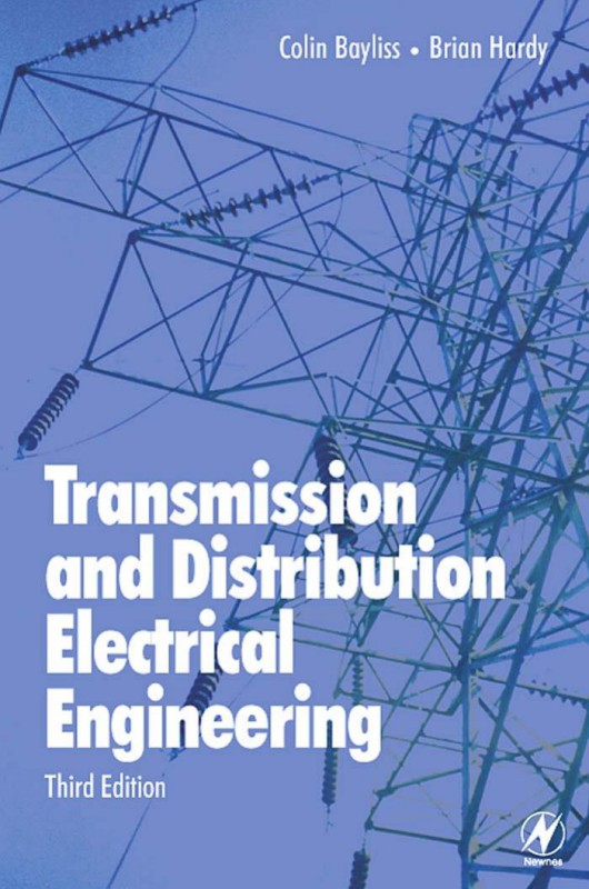
(Ebook PDF) Transmission and Distribution Electrical Engineering 3rd edition by Colin Bayliss, Brian Hardy 0080468136 9780750666732 9780080468136 full chapters
$50.00 Original price was: $50.00.$25.00Current price is: $25.00.
Authors:C.R. Bayliss; B.J. Hardy , Series:Electrical Engineering [171] , Author sort:Bayliss, C.R. & Hardy, B.J. , Languages:Languages:eng , Published:Published:Jun 2007 , Publisher:Newnes
Transmission and Distribution Electrical Engineering 3rd edition by Colin Bayliss, Brian Hardy – Ebook PDF Instant Download/DeliveryISBN: 9780750666732, 9780080468136, 0080468136
Full download Transmission and Distribution Electrical Engineering 3rd edition after payment.
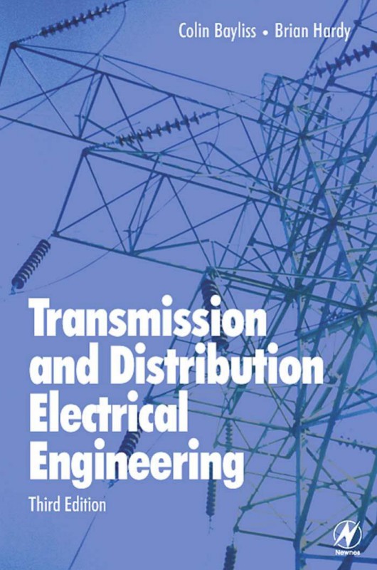
Product details:
ISBN-10 : 0080468136
ISBN-13 : 9780750666732 9780080468136
Author : Colin Bayliss, Brian Hardy
Dramatic power outages in North America, and the threat of a similar crisis in Europe, have made the planning and maintenance of the electrical power grid a newsworthy topic.
Most books on transmission and distribution electrical engineering are student texts that focus on theory, brief overviews, or specialized monographs. Colin Bayliss and Brian Hardy have produced a unique and comprehensive handbook aimed squarely at the engineers and planners involved in all aspects of getting electricity from the power plant to the user via the power grid. The resulting book is an essential read, and a hard-working reference for all engineers, technicians, managers and planners involved in electricity utilities, and related areas such as generation, and industrial electricity usage.
Transmission and Distribution Electrical Engineering 3rd Table of contents:
Chapter 1 System Studies
1.1 Introduction
1.2 Load flow
1.2.1 Purpose
1.2.2 Sample study
1.3 System stability
1.3.1 Introduction
1.3.2 Analytical aspects
1.3.3 Steady state stability
1.3.4 Transient stability
1.3.5 Dynamic stability
1.3.6 Effect of induction motors
1.3.7 Data requirements and interpretation of transient stability studies
1.3.8 Case studies
1.4 Short circuit analysis
1.4.1 Purpose
1.4.2 Sample study
Chapter 2 Drawings and Diagrams
2.1 Introduction
2.2 Block diagrams
2.3 Schematic diagrams
2.3.1 Method of representation
2.3.2 Main circuits
2.3.3 Control, signalling and monitoring circuits
2.4 Manufacturers’ drawings
2.4.1 Combined wiring/cabling diagrams
2.4.2 British practice
2.4.3 European practice
2.4.4 Other systems
2.5 Computer aided design (CAD)
2.6 Case study
2.7 Graphical symbols
Appendix A: Relay identification – numerical codes
Appendix B: Comparison between German, British, US/Canadian and international symbols
B1 General circuit elements
B2 Operating mechanisms
B3 Switchgear
Chapter 3 Substation Layouts
3.1 Introduction
3.2 Substation design considerations
3.2.1 Security of supply
3.2.2 Extendibility
3.2.3 Maintainability
3.2.4 Operational flexibility
3.2.5 Protection arrangements
3.2.6 Short circuit limitations
3.2.7 Land area
3.2.8 Cost
3.3 Alternative layouts
3.3.1 Single busbar
3.3.2 Transformer feeder
3.3.3 Mesh
3.3.4 Ring
3.3.5 Double busbar
3.3.6 1½ Circuit breaker
3.4 Space requirements
3.4.1 Introduction
3.4.2 Safety clearances
3.4.3 Phase–phase and phase–earth clearances
Chapter 4 Substation Auxiliary Power Supplies
4.1 Introduction
4.2 DC supplies
4.2.1 Battery and charger configurations
4.2.2 Battery charger components
4.2.3 Installation requirements
4.2.4 Typical enquiry data – DC switchboard
4.3 Batteries
4.3.1 Introduction
4.3.2 Battery capacity
4.3.3 Characteristics of batteries
4.3.4 Battery sizing calculations
4.3.5 Typical enquiry data
4.4 AC supplies
4.4.1 Power sources
4.4.2 LVAC switchboard fault level
4.4.3 Auxiliary transformer LV connections
4.4.4 Allowance for future extension
4.4.5 Typical enquiry data
4.4.6 Earthing transformer selection
4.4.7 Uninterruptible power supplies
Chapter 5 Current and Voltage Transformers
5.1 Introduction
5.2 Current transformers
5.2.1 Introduction
5.2.2 Protection CT classifications
5.2.3 Metering CTs
5.2.4 Design and construction considerations
5.2.5 Terminal markings
5.2.6 Specifications
5.3 Voltage transformers
5.3.1 Introduction
5.3.2 Electromagnetic VTs
5.3.3 Capacitor VTs
5.3.4 Specifications
5.4 Future trends
Chapter 6 Insulators
6.1 Introduction
6.2 Insulator materials
6.2.1 Polymeric and resin materials
6.2.2 Glass and porcelain
6.3 Insulator types
6.3.1 Post insulators
6.3.2 Cap and pin insulators
6.3.3 Long rod
6.4 Pollution control
6.4.1 Environment/creepage distances
6.4.2 Remedial measures
6.4.3 Calculation of specific creepage path
6.5 Insulator specification
6.5.1 Standards
6.5.2 Design characteristics
6.6 Tests
6.6.1 Sample and routine tests
6.6.2 Technical particulars
Chapter 7 Substation Building Services
7.1 Introduction
7.2 Lighting
7.2.1 Terminology
7.2.2 Internal lighting
7.2.3 External lighting
7.2.4 Control
7.3 Distribution characterization
7.4 Heating, ventilation and air-conditioning
7.4.1 Air circulation
7.4.2 Air-conditioning
7.4.3 Heating
7.5 Fire detection and suppression
7.5.1 Introduction
7.5.2 Fire extinguishers
7.5.3 Access, first aid and safety
7.5.4 Fire detection
7.5.5 Fire suppression
7.5.6 Cables, control panels and power supplies
Chapter 8 Earthing and Bonding
8.1 Introduction
8.2 Design criteria
8.2.1 Touch and step voltages
8.2.2 Touch and step voltage limits
8.3 Substation earthing calculations
8.3.1 Environmental conditions
8.3.2 Earthing materials
8.3.3 Earth resistance and earth potential rise
8.3.4 Hazard voltage tolerable limits
8.4 Computer simulation
References
Chapter 9 Insulation Co-ordination
9.1 Introduction
9.2 System voltages
9.2.1 Power frequency voltage
9.2.2 Overvoltages
9.3 Clearances
9.3.1 Air
9.3.2 SF[sub(6)]9.4 Procedures for co-ordination
9.4.1 The IEC standard approach
9.4.2 Statistical approach
9.4.3 Non-statistical approach
9.5 Surge protection
9.5.1 Rod or spark gaps
9.5.2 Surge arresters
References
Chapter 10 Relay Protection
10.1 Introduction
10.2 System configurations
10.2.1 Faults
10.2.2 Unearthed systems
10.2.3 Impedance earthed systems
10.2.4 Solidly earthed systems
10.2.5 Network arrangements
10.3 Power system protection principles
10.3.1 Discrimination by time
10.3.2 Discrimination by current magnitude
10.3.3 Discrimination by time and fault direction
10.3.4 Unit protection
10.3.5 Signalling channel assistance
10.4 Current relays
10.4.1 Introduction
10.4.2 Inverse definite minimum time lag (IDMTL) relays
10.4.3 Alternative characteristic curves
10.4.4 Plotting relay curves on log/log graph paper
10.4.5 Current relay application examples
10.5 Differential protection schemes
10.5.1 Biased differential protection
10.5.2 High impedance protection
10.5.3 Transformer protection application examples
10.5.4 Pilot wire unit protection
10.5.5 Busbar protection
10.6 Distance relays
10.6.1 Introduction
10.6.2 Basic principles
10.6.3 Relay characteristics
10.6.4 Zones of protection
10.6.5 Switched relays
10.6.6 Typical overhead transmission line protection schemes
10.7 Auxiliary relays
10.7.1 Tripping and auxiliary
10.7.2 AC auxiliary relays
10.7.3 Timers
10.7.4 Undervoltage
10.7.5 Underfrequency
10.8 Computer assisted grading exercise
10.8.1 Basic input data
10.8.2 Network fault levels
10.8.3 CT ratios and protection devices
10.8.4 Relay settings
10.9 Practical distribution network case study
10.9.1. Introduction
10.9.2. Main substation protection
10.9.3. Traction system protection
10.9.4. 21 kV distribution system and protection philosophy
10.9.5. 21 kV pilot wire unit protection
10.9.6. 21 kV system back-up protection
10.9.7. Use of earth fault indicators
10.9.8. Summary
10.10 Recent advances in control, protection and monitoring
10.10.1 Background
10.10.2 Developments
References
Chapter 11 Fuses and Miniature Circuit Breakers
11.1 Introduction
11.2 Fuses
11.2.1 Types and standards
11.2.2 Definitions and terminology
11.2.3 HRC fuses
11.2.4 High voltage fuses
11.2.5 Cartridge fuse construction
11.3 Fuse operation
11.3.1 High speed operation
11.3.2 Discrimination
11.3.3 Cable protection
11.3.4 Motor protection
11.3.5 Semiconductor protection
11.4 Miniature circuit breakers
11.4.1 Operation
11.4.2 Standards
11.4.3 Application
References
Chapter 12 Cables
12.1 Introduction
12.2 Codes and standards
12.3 Types of cables and materials
12.3.1 General design criteria
12.3.2 Cable construction
12.3.3 Submarine cables
12.3.4 Joints and terminations
12.4 Cable sizing
12.4.1 Introduction
12.4.2 Cables laid in air
12.4.3 Cables laid direct in ground
12.4.4 Cables laid in ducts
12.4.5 Earthing and bonding
12.4.6 Short circuit ratings
12.4.7 Calculation examples
12.5 Calculation of losses in cables
12.5.1 Dielectric losses
12.5.2 Screen or sheath losses
12.6 Fire properties of cables
12.6.1 Introduction
12.6.2 Toxic and corrosive gases
12.6.3 Smoke emission
12.6.4 Oxygen index and temperature index
12.6.5 Flame retardance/flammability
12.6.6 Fire resistance
12.6.7 Mechanical properties
12.7 Control and communication cables
12.7.1 Low voltage and multicore control cables
12.7.2 Telephone cables
12.7.3 Fibre optic cables
12.8 Cable management systems
12.8.1 Standard cable laying arrangements
12.8.2 Computer aided cable installation systems
12.8.3 Interface definition
References
Chapter 13 Switchgear
13.1 Introduction
13.2 Terminology and standards
13.3 Switching
13.3.1 Basic principles
13.3.2 Special switching cases
13.3.3 Switches and disconnectors
13.3.4 Contactors
13.4 Arc quenching media
13.4.1 Introduction
13.4.2 Sulphur hexafluoride (SF[sub(6)])
13.4.3 Vacuum
13.4.4 Oil
13.4.5 Air
13.5 Operating mechanisms
13.5.1 Closing and opening
13.5.2 Interlocking
13.5.3 Integral earthing
13.6 Equipment specifications
13.6.1 12 kV metal-clad indoor switchboard example
13.6.2 Open terminal 145 kV switchgear examples
13.6.3 Distribution system switchgear example
13.6.4 Distribution ring main unit
References
Chapter 14 Power Transformers
14.1 Introduction
14.2 Standards and principles
14.2.1 Basic transformer action
14.2.2 Transformer equivalent circuit
14.2.3 Voltage and current distribution
14.2.4 Transformer impedance representation
14.2.5 Tap changers
14.2.6 Useful standards
14.3 Voltage, impedance and power rating
14.3.1 General
14.3.2 Voltage drop
14.3.3 Impedance
14.3.4 Voltage ratio and tappings – general
14.3.5 Voltage ratio with off-circuit tappings
14.3.6 Voltage ratio and on-load tappings
14.3.7 Basic insulation levels (BIL)
14.3.8 Vector groups and neutral earthing
14.3.9 Calculation example to determine impedance and tap range
14.4 Thermal design
14.4.1 General
14.4.2 Temperature rise
14.4.3 Loss of life expectancy with temperature
14.4.4 Ambient temperature
14.4.5 Solar heating
14.4.6 Transformer cooling classifications
14.4.7 Selection of cooling classification
14.4.8 Change of cooling classification in the field
14.4.9 Capitalization of losses
14.5 Constructional aspects
14.5.1 Cores
14.5.2 Windings
14.5.3 Tanks and enclosures
14.5.4 Cooling plant
14.5.5 Low fire risk types
14.5.6 Neutral earthing transformers
14.5.7 Reactors
14.6 Accessories
14.6.1 General
14.6.2 Buchholz relay
14.6.3 Sudden pressure relay and gas analyser relay
14.6.4 Pressure relief devices
14.6.5 Temperature monitoring
14.6.6 Breathers
14.6.7 Miscellaneous
14.6.8 Transformer ordering details
References
Chapter 15 Substation and Overhead Line Foundations
15.1 Introduction
15.2 Soil investigations
15.3 Foundation types
15.4 Foundation design
15.5 Site works
15.5.1 Setting out
15.5.2 Excavation
15.5.3 Piling
15.5.4 Earthworks
15.5.5 Concrete
15.5.6 Steelwork fixings
Chapter 16 Overhead Line Routing
16.1 Introduction
16.2 Routing objectives
16.3 Preliminary routing
16.3.1 Survey equipment requirements
16.3.2 Aerial survey
16.3.3 Ground survey
16.3.4 Ground soil conditions
16.3.5 Wayleave, access and terrain
16.3.6 Optimization
16.4 Detailed line survey and profile
16.4.1 Accuracy requirements
16.4.2 Profile requirements
16.4.3 Computer aided techniques
Chapter 17 Structures, Towers and Poles
17.1 Introduction
17.2 Environmental conditions
17.2.1 Typical parameters
17.2.2 Effect on tower or support design
17.2.3 Conductor loads
17.3 Structure design
17.3.1 Lattice steel tower design considerations
17.3.2 Tower testing
17.4 Pole and tower types
17.4.1 Pole structures
17.4.2 Tower structures
References
Chapter 18 Overhead Line Conductor and Technical Specifications
18.1 Introduction
18.2 Environmental conditions
18.3 Conductor selection
18.3.1 General
18.3.2 Types of conductor
18.3.3 Aerial bundled conductor and BLX
18.3.4 Conductor breaking strengths
18.3.5 Bi-metal connectors
18.3.6 Corrosion
18.4 Calculated electrical ratings
18.4.1 Heat balance equation
18.4.2 Power carrying capacity
18.4.3 Corona discharge
18.4.4 Overhead line calculation example
18.5 Design spans, clearances and loadings
18.5.1 Design spans
18.5.2 Conductor and earth wire spacing and clearances
18.5.3 Broken wire conditions
18.5.4 Conductor tests/inspections
18.6 Overhead line fittings
18.6.1 Fittings related to aerodynamic phenomena
18.6.2 Suspension clamps
18.6.3 Sag adjusters
18.6.4 Miscellaneous fittings
18.7 Overhead line impedance
18.7.1 Inductive reactance
18.7.2 Capacitive reactance
18.7.3 Resistance
18.8 Substation busbar selection – case study
18.8.1 Introduction
18.8.2 Conductor diameter/current carrying capacity
18.8.3 Conductor selection on weight basis
18.8.4 Conductor short circuit current capability
18.8.5 Conductor support arrangements
References
Chapter 19 Testing and Commissioning
19.1 Introduction
19.2 Quality assurance
19.2.1 Introduction
19.2.2 Inspection release notice
19.2.3 Partial acceptance testing
19.2.4 System acceptance testing
19.2.5 Documentation and record systems
19.3 Works inspections and testing
19.3.1 Objectives
19.3.2 Specifications and responsibilities
19.3.3 Type tests
19.3.4 Routine production tests
19.4 Site inspection and testing
19.4.1 Pre-commissioning and testing
19.4.2 Maintenance inspection
19.4.3 On-line inspection and testing
19.5 Testing and commissioning methods
19.5.1 Switchgear
19.5.2 Transformers
19.5.3 Cables
19.5.4 Protection
Appendix A: Commissioning test procedure requirements
Appendix B: Drawings, diagrams and manuals
Chapter 20 Electromagnetic Compatibility
20.1 Introduction
20.2 Standards
20.3 Compliance
20.4 Testing
20.4.1 Introduction
20.4.2 Magnetic field radiated emission measurements
20.4.3 Electric field radiated emission measurements
20.4.4 Conducted emission measurements
20.4.5 Immunity testing
20.5 Screening
20.5.1 Introduction
20.5.2 The use of screen wire
20.5.3 The use of screen boxes and Faraday enclosures
20.5.4 The use of screen floors in rooms
20.6 Typical useful formulae
20.6.1 Decibel reference levels
20.6.2 Field strength calculations
20.6.3 Mutual inductance between two long parallel pairs of wires
20.6.4 Attenuation factors
20.7 Case studies
20.7.1 Screening power cables
20.7.2 Measurement of field strengths
References
Chapter 21 Supervisory Control and Data Acquisition
21.1 Introduction
21.2 Programmable logic controllers
21.2.1 Functions
21.2.2 PLC selection
21.2.3 Application example
21.3 Power line carrier communication links
21.3.1 Introduction
21.3.2 Power line carrier communication principles
21.4 Supervisory control and data acquisition
21.4.1 Introduction
21.4.2 Typical characteristics
21.4.3 Design issues
21.4.4 Example (Channel Tunnel)
21.5 Software management
21.5.1 Software – a special case
21.5.2 Software life cycle
21.5.3 Software implementation practice
21.5.4 Software project management
References
Chapter 22 Project Management
22.1 Introduction
22.2 Project evaluation
22.2.1 Introduction
22.2.2 Financial assessment
22.2.3 Economic assessment
22.3 Financing
22.3.1 Responsibilities for funding
22.3.2 Cash flow
22.3.3 Sources of finance
22.3.4 Export credit agencies
22.3.5 Funding risk reduction
22.3.6 Use of private finance
22.4 Project phases
22.4.1 The project life cycle
22.4.2 Cash flow
22.4.3 Bonds
22.4.4 Advance payments and retentions
22.4.5 Insurances
22.4.6 Project closeout
22.5 Terms and conditions of contract
22.5.1 Time, cost and quality
22.5.2 Basic types of contract
22.5.3 Standard terms and conditions of contract
22.5.4 Key clauses
22.6 Tendering
22.6.1 Choosing the contractor
22.6.2 Estimating
22.6.3 Tender evaluation
22.7 Model forms of contract – exercise
Appendix A: Project definition/questionnaire
Appendix B: Bidding checklist
Chapter 23 Distribution Planning
23.1 Introduction
23.2 Definitions
23.2.1 Demand or average demand
23.2.2 Maximum demand (MD)
23.2.3 Demand factor
23.2.4 Utilization factor (UF)
23.2.5 Load factor (LDF)
23.2.6 Diversity factor (DF)
23.2.7 Coincident factor (CF)
23.2.8 Load diversity
23.2.9 Loss factor (LSF)
23.2.10 Load duration
23.2.11 Loss equivalent hours
23.2.12 Peak responsibility factor (PRF)
23.3 Load forecasting
23.3.1 Users of load forecasts
23.3.2 The preparation of load forecasts
23.3.3 The micro load forecast
23.3.4 The macro load forecast
23.3.5 Nature of the load forecast
23.4 System parameters
23.4.1 Distribution feeder arrangements
23.4.2 Voltage drop calculations
23.4.3 Positive sequence resistance
23.4.4 Inductive reactance
23.4.5 Economic loading of distribution feeders and transformers
23.4.6 System losses
23.5 System reliability
23.5.1 Introduction
23.5.2 Reliability functions
23.5.3 Predictability analysis
23.6 Drawings and materials take off
Chapter 24 Power Quality – Harmonics in Power Systems
24.1 Introduction
24.2 The nature of harmonics
24.2.1 Introduction
24.2.2 Three phase harmonics
24.3 The generation of harmonics
24.3.1 General
24.3.2 Transformers
24.3.3 Converters
24.3.4 The thyristor bridge
24.3.5 Railway and tramway traction systems
24.3.6 Static VAr compensators and balancers
24.4 The effects of harmonics
24.4.1 Heating effects of harmonics
24.4.2 Harmonic overvoltages
24.4.3 Resonances
24.4.4 Interference
24.5 The limitation of harmonics
24.5.1 Harmonic filters
24.5.2 Capacitor detuning
24.6 Ferroresonance and subharmonics
24.6.1 Introduction
24.6.2 A physical description of ferroresonance
24.6.3 Subharmonics
24.6.4 Interharmonics
24.7 Harmonic studies
24.7.1 The requirement
24.7.2 The studies
24.7.3 Measurement
24.8 Case studies
References
Chapter 25 Power Quality – Voltage Fluctuations
25.1 Introduction
25.2 The nature and cause of voltage disturbances in power systems
25.2.1 Short-term interruptions and voltage dips and peaks
25.2.2 Voltage fluctuations
25.2.3 Voltage flicker
25.2.4 Slow-voltage fluctuations
25.2.5 Voltage unbalance
25.2.6 Step-change events
25.3 Solutions
25.3.1 Energy storage
25.3.2 Balancing
25.3.3 Static VAr compensators
25.3.4 The STATCOM
25.4 Case study
References
Chapter 26 Fundamentals
26.1 Introduction
26.2 Symbols and nomenclature
26.2.1 Symbols
26.2.2 Units and conversion tables
26.3 Alternating quantities
26.4 Vector representation
26.5 Vector algebra
26.5.1 The j operator
26.5.2 Exponential vector format
26.5.3 Polar co-ordinate vector format
26.5.4 Algebraic operations on vectors
26.5.5 The h operator
26.6 Sequence components
26.6.1 Theoretical background
26.6.2 Calculation methodology and approximations
26.6.3 Interpretation
26.7 Network fault analysis
26.7.1 Introduction
26.7.2 Fundamental formulae
26.7.3 Simplified network reduction example
26.8 Design optimization
26.8.1 Introduction
26.8.2 Technical problems
26.8.3 Loss reduction
26.8.4 Communication link gain or attenuation
26.8.5 Reactive compensation
26.8.6 Power factor correction calculation procedures
People also search for Transmission and Distribution Electrical Engineering 3rd:
transmission and distribution electrical engineering book
transmission and distribution electrical engineering colin bayliss
transmission and distribution electrical engineering 4th edition
transmission and distribution electrical engineering fourth edition
transmission and distribution electrical engineering bayliss
You may also like…
eBook PDF
(Ebook PDF) Basic Electrical Engineering 4th edition by Wadhwa 9788122429473 full chapters
eBook PDF
Electrical Distribution Engineering 3rd Edition by Anthony Pansini 0849382491 9780849382499
eBook MOBI
(Ebook PDF) Electrical Engineering Experiments 1st edition by Chhalotra 9781683921158 full chapters

