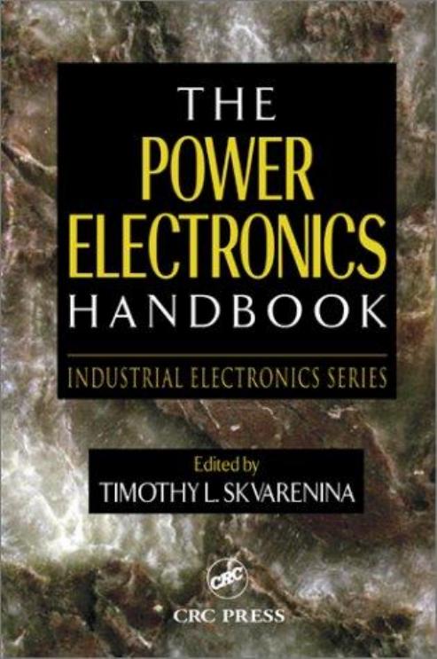
(Ebook PDF) The Power Electronics Handbook Industrial Electronics Series 1st edition by Timothy Skvarenina 1351836536 9781351836531 full chapters
$50.00 Original price was: $50.00.$25.00Current price is: $25.00.
Authors:Timothyl , Series:Electrical Engineering [231] , Tags:Electrical , Author sort:Timothyl , Languages:Languages:eng , Published:Published:Nov 2002 , Publisher:CRC Press , Comments:Comments:This book contains information obtained from authentic and highly regarded sources. Reprinted material is quoted withpermission, and sources are indicated. A wide variety of references are listed. Reasonable efforts have been made to publishreliable data and information, but the authors and the publisher cannot assume responsibility for the validity of all materialsor for the consequences of their use.Neither this book nor any part may be reproduced or transmitted in any form or by any means, electronic or mechanical,including photocopying, microfilming, and recording, or by any information storage or retrieval system, without priorpermission in writing from the publisher.All rights reserved. Authorization to photocopy items for internal or personal use, or the personal or internal use of specificclients, may be granted by CRC Press LLC, provided that $1.50 per page photocopied is paid directly to Copyright ClearanceCenter, 222 Rosewood Drive, Danvers, MA 01923 USA The fee code for users of the Transactional Reporting Service isISBN 0-8493-7336-0/02/$0.00+$1.50. The fee is subject to change without notice. For organizations that have been granteda photocopy license by the CCC, a separate system of payment has been arranged.
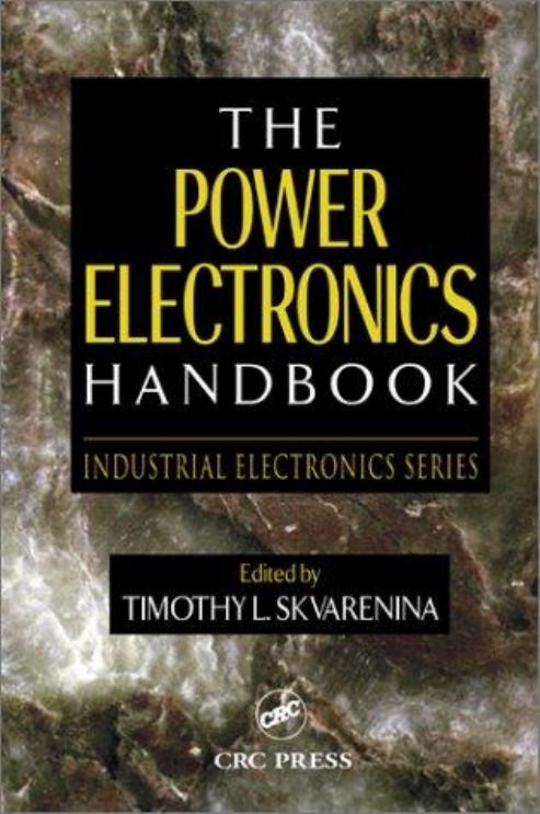
The Power Electronics Handbook Industrial Electronics Series 1st edition by Timothy L. Skvarenina – Ebook PDF Instant Download/DeliveryISBN: 1351836536, 9781351836531
Full download The Power Electronics Handbook Industrial Electronics Series 1st edition after payment.
Product details:
ISBN-10 : 1351836536
ISBN-13 : 9781351836531
Author : Timothy L. Skvarenina
Less expensive, lighter, and smaller than its electromechanical counterparts, power electronics lie at the very heart of controlling and converting electric energy, which in turn lies at the heart of making that energy useful. From household appliances to space-faring vehicles, the applications of power electronics are virtually limitless. Until now, however, the same could not be said for access to up-to-date reference books devoted to power electronics. Written by engineers for engineers, The Power Electronics Handbook covers the full range of relevant topics, from basic principles to cutting-edge applications. Compiled from contributions by an international panel of experts and full of illustrations, this is not a theoretical tome, but a practical and enlightening presentation of the usefulness and variety of technologies that encompass the field. For modern and emerging applications, power electronic devices and systems must be small, efficient, lightweight, controllable, reliable, and economical. The Power Electronics Handbook is your key to understanding those devices, incorporating them into controllable circuits, and implementing those systems into applications from virtually every area of electrical engineering.
The Power Electronics Handbook Industrial Electronics Series 1st Table of contents:
Part I Power Electronic Devices
1 Power Electronics
1.1 Overview
Thyristor and Triac
Gate Turn-Off Thyristor
Reverse-Conducting Thyristor (RCT) and Asymmetrical Silicon-Controlled Rectifier (ASCR)
Power Transistor
Power MOSFET
Insulated-Gate Bipolar Transistor (IGBT)
MOS-Controlled Thyristor (MCT)
1.2 Diodes
Characteristics
Principal Ratings for Diodes
Maximum Average Forward Current
Peak Inverse Voltage
Maximum Surge Current
Maximum Junction Temperature
Rectifier Circuits
Testing a Power Diode
Protection of Power Diodes
1.3 Schottky Diodes
Characteristics
Data Specifications
Testing of Schottky Diodes
1.4 Thyristors
The Basics of Silicon-Controlled Rectifiers (SCR)
Characteristics
SCR Turn-Off Circuits
SCR Ratings
The DIAC
The Triac
The Silicon-Controlled Switch
The Gate Turn-Off Thyristor
Data Sheet for a Typical Thyristor
1.5 Power Bipolar Junction Transistors
The Volt-Ampere Characteristics of a BJT
BJT Biasing
BJT Power Losses
BJT Testing
BJT Protection
1.6 MOSFETs
Static Characteristics
Breakdown Voltage
On-Resistance
Transconductance
Threshold Voltage
Diode Forward Voltage (VF or VSD)
Power Dissipation
Dynamic Characteristics
Switching and Transient Response
Gate Charge
dV/dt Capability
Applications
Portable Electronics and Wireless Communication
Automotive
1.7 General Power Semiconductor Switch Requirements
1.8 Gate Turn-Off Thyristors
GTO Forward Conduction
GTO Turn-Off and Forward Blocking
Practical GTO Turn-Off Operation
Dynamic Avalanche
Non-Uniform Turn-Off Process among GTO Cells
Current Filamentation Caused by Storage Time Difference
Current Filamentation Caused by Onset of Dynamic Avalanche
Summary
1.9 Insulated Gate Bipolar Transistors
IGBT Structure and Operation
1.10 Gate-Commutated Thyristors and Other Hard-Driven GTOs
Unity Gain Turn-Off Operation
Traditional GTO Gate Drive Circuit
Unity Turn-Off Gain of the GTO
Advantages of Unity Gain Turn-Off
Hard-Driven GTOs
IGCT
MTO
ETO
Conclusions
1.11 Comparison Testing of Switches
Pulse Tester Used for Characterization
Devices Used for Comparison
Unity Gain Verification
Gate Drive Circuits
Forward Conduction Loss Characterization
Switching Tests
Discussion
Comparison Conclusions
Part II Power Electronic Circuits and Controls
2 DC-DC Converters
2.1 Overview
2.2 Choppers
One-Quadrant Choppers
Step-Down (Buck) Converter
Step-Up (Boost) Converter
Two-Quadrant Choppers
Four-Quadrant Choppers
2.3 Buck Converters
Ideal Buck Circuit
Continuous-Conduction Mode
Discontinuous-Conduction Mode
Output Voltage Ripple
2.4 Boost Converters
Ideal Boost Circuit
Continuous-Conduction Mode
Discontinuous-Conduction Mode
Output Voltage Ripple
2.5 Cúk Converter
Nonisolated Operation
Practical Cúk Converter
2.6 Buck–Boost Converters
Circuit Analysis
Continuous-Current Mode
Discontinuous-Current Mode
Small Signal Transfer Functions
Component Selection
Inductor Value
Capacitor Value
Main Power Switch and Output Power Diode
Flyback Power Stage
Summary
References
References
3 AC-AC Conversion
3.1 Introduction
3.2 Cycloconverters
3.3 Matrix Converters
References
4 Rectifiers
4.1 Uncontrolled Single-Phase Rectifiers
Single-Phase Half-Wave Rectifiers
Operation
Important Diode Current Characteristics
Peak Forward Current
rms Forward Current
Mean Forward Current
Single Cycle Surge Current
Important Diode Voltage Characteristics
Average Output Voltage
Repetitive Peak Reverse Voltage
Forward Voltage Drop
Nonrepetitive Peak Reverse Voltage
Single-Phase Full-Wave Rectifiers
Operation
Important Diode Current Characteristics
Peak Rectified Forward Current
rms Forward Current
Average Forward Current
Single-Cycle Surge Current
Important Diode Voltage Characteristics
Average Output Voltage
Repetitive Peak Reverse Voltage
Forward Voltage Drop
Nonrepetitive Peak Reverse Voltage
4.2 Uncontrolled and Controlled Rectifiers
Uncontrolled Rectifiers
Mechanics of Diode Conduction
Single-Phase Half-Wave Rectifier Circuits
Full-Wave Rectifiers
Three-Phase Rectifiers (Half-Wave and Full-Wave)
Average Output Voltage
Influence of Three-Phase Rectification on the Power System
Why Diode Rectifiers Generate Harmonics
Harmonic Limits Based on IEEE Std. 519-1992
Harmonic Mitigating Techniques
Three-Phase Line Reactors
DC-Link Choke
Passive Filters
Phase Multiplication
Active Harmonic Compensation
Controlled Rectifiers
Increasing Applied Voltage
High dv/dt
Temperature
Gate Current Injection
Gate Circuit Requirements
Single-Phase H-Bridge Rectifier Circuits with Thyristors
Three-Phase Controlled AC-to-DC Rectifier Systems
Aerage Output Voltage
HVDC Transmission Systems
Power System Interaction with Three-Phase Thyristor AC-to-DC Rectifier Systems
Conclusion
4.3 Three-Phase Pulse-Width-Modulated Boost-Type Rectifiers
Introduction
Indirect Current Control of a Unity Power Factor Sinusoidal Current Boost-Type Rectifier
Example
Solution
5 Inverters
5.1 Overview
Fundamental Issues
Single-Phase Inverters
Three-Phase Inverters
Multilevel Inverters
Line-Commutated Inverters
5.2 DC-AC Conversion
Basic DC-AC Converter Connections (Square-Wave Operation)
Control of the Output Voltage
Harmonics in the Output Voltage
Filtering of Output Voltage
Practical Realization of Basic Connections
Special Realizations (Application of Resonant Converter Techniques)
5.3 Resonant Converters
Survey of Second-Order Resonant Circuits
Load Resonant Converters
Input Time Functions
Series-Resonant Converters
Discontinuous Mode
Parallel-Resonant Converters
Class E Converter
Series- and Parallel-Loaded Resonant DC-DC Converters
Resonant Switch Converters
ZCS Resonant Converters
ZVS Resonant Converter
Summary and Comparison of ZCS and ZVS Converters
Two-Quadrant ZVS Resonant Converters
Resonant DC-Link Converters with ZVS
5.4 Series-Resonant Inverters
Voltage-Source Series-Resonant Inverters
Circuit and Waveforms
Operation below Resonance
Operation above Resonance
Voltage Transfer Function
Voltage-Source Parallel-Resonant Inverters
Circuit and Waveforms
Voltage Transfer Function
Voltage-Source Series-Parallel-Resonant Inverters
Circuit and Waveforms
Voltage Transfer Function
Summary
5.5 Resonant DC-Link Inverters
The Resonant DC-Link Inverter
Disadvantages of the RDCLI
Reducing the Peak Voltage on the DC-Link
Achieving Continuous PWM Control with the RDCLI: The Quasi-RDCLI
The Parallel-Resonant DC-Link Inverter
Current Research Trends
5.6 Auxiliary Resonant Commutated Pole Inverters
Losses in Hard-Switched Inverters
Introduction
Hard-Switched Phase Leg
Transistor Turn-On Losses
Transistor Turn-Off Losses
Analysis of ARCP Phase Leg
ARCP Circuit Description
Low-to-High Commutation from Diode
Low-to-High Commutation from Switch, Low Current
Low-to-High Commutation from Switch, High Current
Simulation of ARCP Phase Leg
Analysis of ARCP H-Bridge
Circuit Description and Pulse Width Modulation
H-Bridge Loss Analysis
Analysis of ARCP Three-Phase Inverter
Description of ARCP Three-Phase Circuit
Computer Study
Summary
6 Multilevel Converters
6.1 Introduction
6.2 Multilevel Voltage Source Modulation
6.3 Fundamental Multilevel Converter Topologies
Diode-Clamped Multilevel Converters
Flying-Capacitor Multilevel Converters
Cascaded H-Bridge Multilevel Converters
Multilevel H-Bridge Converters
6.4 Cascaded Multilevel Converter Topologies
Cascaded Multilevel Converters
Cascaded Multilevel H-Bridge Converters
6.5 Multilevel Converter Laboratory Examples
Three-Level Diode-Clamped Inverter
The Cascade-3/2 Inverter
The Cascade-5/3H Inverter
6.6 Conclusion
7 Modulation Strategies
7.1 Introduction
7.2 Six-Step Modulation
7.3 Pulse Width Modulation
PWM Signals with DC Average
PWM Signals for AC Output
7.4 Third Harmonic Injection for Voltage Boost of SPWM Signals
7.5 Generation of PWM Signals Using Microcontrollers and DSPs
7.6 Voltage Source–Based Current Regulation
7.7 Hysteresis Feedback Control
Introduction
Principles of the Hysteresis Feedback Control Circuits
Design Procedure
Design Example
Simulation Results
Experimental Results
Conclusions
7.8 Space-Vector Pulse Width Modulation
How the SVPWM Works
Implementation
Switching Signals
8 Sliding-Mode Control of Switched-Mode Power Supplies
8.1 Introduction
8.2 Introduction to Sliding-Mode Control
8.3 Basics of Sliding-Mode Theory
Existence Condition
Hitting Conditions
System Description in Sliding Mode: Equivalent Control
Stability
8.4 Application of Sliding-Mode Control to DC-DC Converters—Basic Principle
8.5 Sliding-Mode Control of Buck DC-DC Converters
Phase-Plane Description
Selection of the Sliding Line
Existence Condition
Current Limitation
8.6 Extension to Boost and Buck–Boost DC-DC Converters
Stability Analysis
8.7 Extension to Cúk and SEPIC DC-DC Converters
Existence Condition
Hitting Condition
Stability Condition
8.8 General-Purpose Sliding-Mode Control Implementation
8.9 Conclusions
Part III Applications and Systems Considerations
9 DC Motor Drives
9.1 DC Motor Basics
9.2 DC Speed Control
9.3 DC Drive Basics
9.4 Transistor PWM DC Drives
9.5 SCR DC Drives
10 AC Machines Controlled as DC Machines (Brushless DC Machines/Electronics)
10.1 Introduction
10.2 Machine Construction
Permanent Magnets
Stator Windings
10.3 Motor Characteristics
Mathematical Model
10.4 Power Electronic Converter
Unipolar Excitation
Fault-Tolerant Configuration
Current Source Inverter
10.5 Position Sensing
Position Sensorless Control
10.6 Pulsating Torque Components
10.7 Torque-Speed Characteristics
10.8 Applications
11 Control of Induction Machine Drives
11.1 Introduction
11.2 Scalar Induction Machine Control
11.3 Vector Control of Induction Machines
Vector Formulation of the Induction Machine
Induction Machine Dynamic Model
Field-Oriented Control of the Induction Machine
Direct Torque Control of the Induction Machine
Space Vector Modulation
Direct Torque Control Concept
11.4 Summary
12 Permanent-Magnet Synchronous Machine Drives
12.1 Introduction
12.2 Construction of PMSM Drive Systems
12.3 Simulation and Model
12.4 Controlling the PMSM
Current-Based Drives
Voltage-Based Drives
12.5 Advanced Topics in PMSM Drives
13 Switched Reluctance Machines
13.1 Introduction
Advantages
Disadvantages
13.2 SRM Configuration
13.3 Basic Principle of Operation
Voltage Balance Equation
Energy Conversion
Torque Production
Torque–Speed Characteristics
Region 1
Region 2
Region 3
13.4 Design
13.5 Converter Topologies
13.6 Control Strategies
Control Parameters
Advance Angle Calculation
Voltage-Controlled Drive
Current-Controlled Drive
Advanced Control Strategies
13.7 Sensorless Control
Nonintrusive methods
13.8 Applications
14 Step Motor Drives
14.1 Introduction
14.2 Types and Operation of Step Motors
Principle of Operation
Variable Reluctance Step Motor
Drive Circuits for Variable Reluctance Step Motors
Permanent Magnet (Can-Stack) Step Motor
Hybrid Step Motor
Drive Circuitry for Permanent Magnet and Hybrid Step Motors
14.3 Step Motor Models
Variable Reluctance Step Motor Model
Bifilar-Wound Hybrid Step Motor Model
Drive Circuit Modeling
14.4 Control of Step Motors
Excitation of Step Motors
Open-Loop Control
15 Servo Drives
15.1 DC Drives
15.2 Induction Motor Drives
PM Synchronous Motor Drive
16 Uninterruptible Power Supplies
16.1 UPS Functions
Power Conditioning
System Integration
Basic
Enhanced
Network
16.2 Static UPS Topologies
Double-Conversion UPS
Line-Interactive UPS
Standby Power Supplies
16.3 The Rotary UPS
16.4 Alternate AC and DC Sources
Batteries
DC Generators
Superconducting Magnetic Energy Storage
AC Generators
17 Power Quality and Utility Interface Issues
17.1 Overview
Harmonics and IEEE 519
Surge Voltages and C62.41
Other Standards Addressing Utility Interface Issues
17.2 Power Quality Considerations
Harmonics
What Are Harmonics?
Harmonic Sequence
Where Do Harmonics Come From?
Effects of Harmonics on the System Voltage
Notching
Effects of Harmonics on Power System Components
Conductors
Three-Phase Neutral Conductors
Transformers
Effects of Harmonics on System Power Factor
Power Factor Correction Capacitors
IEEE Standard 519
17.3 Passive Harmonic Filters
Series Passive Filter
Shunt Passive Filter
Series Passive AC Input Reactor
Low-Pass (Broadband) Filter
Passive Filter Design
Characterizing Harmonic-Producing Loads
Characterizing Power System Voltage and Current Distortion
Determining System Frequency Response Characteristics
Designing Minimum Size Filters Tuned to Individual Harmonic Frequencies
Calculating Harmonic Currents at PCC
Checking against IEEE-519 Recommended Limits
17.4 Active Filters for Power Conditioning
Harmonic-Producing Loads
Identified Loads and Unidentified Loads
Harmonic Current Sources and Harmonic Voltage Sources
Theoretical Approach to Active Filters for Power Conditioning
The Akagi-Nabae Theory
Energy Storage Capacity
Classification of Active Filters
Classification by Objectives: Who Is Responsible for Installing Active Filters?
Classification by System Configuration
Classification by Power Circuit
Classification by Control Strategy
Integrated Series Active Filters
System Configuration
Operating Principle
Control Circuit
Experimental Results
Practical Applications of Active Filters for Power Conditioning
Present Status and Future Trends
Shunt Active Filters for Three-Phase Four-Wire Systems
The 48-MVA Shunt Active Filter for Compensation of Voltage Impact Drop, Variation, and Imbalance
17.5 Unity Power Factor Rectification
Diode Bridge and Phase-Controlled Rectifiers
Standards for Limiting Harmonic Currents
Definitions of Some Common Terms
Passive Solutions
Active Solutions
Single-Phase Active PFC Circuits
Boost Converter–Based PFC
Other CCM Topologies
PFC Converters Utilizing DCM Operation
Single-Stage Solutions
Three-Phase PFC Circuits
Six-Switch PWM Converters
Single-Switch Three-Phase PFCs
Use of Single-Phase PFCs for Three-Phase Applications
Vienna Rectifier
Buck-Derived Three-Phase PFC
Active Filters
Summary
18 Photovoltaic Cells and Systems
18.1 Introduction
18.2 Solar Cell Fundamentals
Conversion of Sunlight to Electricity
Cell Performance
18.3 Utility Interactive PV Applications
The PCU
Simple UI PV System
UI PV System with Battery Backup
18.4 Stand-Alone PV Systems
Systems with No Storage
Systems with Storage
19 Flexible, Reliable, and Intelligent Electrical Energy Delivery Systems
19.1 Introduction
19.2 The Concept of FRIENDS
What is FRIENDS?
Quality Control Centers
Intelligent Function of FRIENDS
19.3 Development of FRIENDS
19.4 The Advanced Power Electronic Technologies within QCCs
Distribution Static Compensator
Dynamic Voltage Restorer
Solid-State Breaker
19.5 Significance of FRIENDS
Flexibility in reconfiguration of the system
Reliability in power supply
Multimenu service for customers
Load leveling and energy conservation
Enhancement of information services to customers
Effective demand-side management
Other functions
19.6 Realization of FRIENDS
19.7 Conclusions
References
People also search for The Power Electronics Handbook Industrial Electronics Series 1st:
the power handbook
the industrial electronics handbook
handbook power electronics
power electronics handbook
the industrial electronics handbook – five volume set
You may also like…
eBook PDF
Principles of Electric Machines and Power Electronics 3rd Edition by Sen 111807887X 9781118078877

