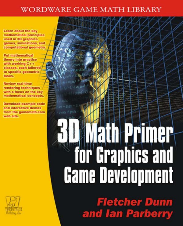
3D Math Primer For Graphics And Game Development 1st Edition by Fletcher Dunn, Ian Parberry ISBN 9781284096200 1284096203
$50.00 Original price was: $50.00.$25.00Current price is: $25.00.
Authors:Fletcher Dunn , Series:Gaming [65] , Author sort:Dunn, Fletcher , Languages:Languages:eng , Published:Published:May 1999 , Publisher:Wordware Publishing
3D Math Primer For Graphics And Game Development 1st Edition by Fletcher Dunn, Ian Parberry – Ebook PDF Instant Download/Delivery. 9781284096200 ,1284096203
Full download 3D Math Primer For Graphics And Game Development 1st Edition after payment
Product details:
ISBN 10: 1284096203
ISBN 13: 9781284096200
Author: Fletcher Dunn, Ian Parberry
3D Math Primer For Graphics And Game Development 1st Edition Table of contents:
Chapter 1 Introduction
1.1 What is 3D Math?
1.2 Why You Should Read This Book
1.3 What You Should Know Before Reading This Book
1.4 Overview
Chapter 2 The Cartesian Coordinate System
2.1 1D Mathematics
Figure 2.1: One dead sheep
Figure 2.2: A number line for the natural numbers
Figure 2.3: A number line for integers (note the ghost sheep for negative numbers)
2.2 2D Cartesian Mathematics
2.2.1 An Example: The Hypothetical City of Cartesia
Figure 2.4: Map of the hypothetical city of Cartesia
2.2.2 Arbitrary 2D Coordinate Spaces
Figure 2.5: A 2D Cartesian coordinate space
Figure 2.6: Screen coordinate space
Figure 2.7: Possible map axis orientations in 2D
2.2.3 Specifying Locations in 2D Using Cartesian Coordinates
Figure 2.8: How to locate a point using 2D Cartesian coordinates
Figure 2.9: Example points labeled with 2D Cartesian coordinates
2.3 From 2D to 3D
2.3.1 Extra Dimension, Extra Axis
Figure 2.10: A 3D Cartesian coordinate space
2.3.2 Specifying Locations in 3D
Figure 2.11: Locating points in 3D
2.3.3 Left-handed vs. Right-handed Coordinate Spaces
Figure 2.12: Left-handed coordinate space
Figure 2.13: Right-handed coordinate space
Figure 2.14: Comparison of left- and right-handed coordinate systems
Figure 2.15: Viewing a left-handed coordinate space from the positive end of the x-axis
2.3.4 Some Important Conventions Used in This Book
Figure 2.16: The left-handed coordinate system conventions used in this book
2.4 Exercises
Figure 2.17
Chapter 3 Multiple Coordinate Spaces
3.1 Why Multiple Coordinate Spaces?
3.2 Some Useful Coordinate Spaces
3.2.1 World Space
3.2.2 Object Space
3.2.3 Camera Space
Figure 3.1: Camera space
3.2.4 Inertial Space
Figure 3.2: Object, inertial, and world spaces
Figure 3.3: The robot’s object space
Figure 3.4: The robot’s inertial space
Figure 3.5: The world space
3.3 Nested Coordinate Spaces
3.4 Specifying Coordinate Spaces
3.5 Coordinate Space Transformations
Figure 3.6: The robot in object space
Figure 3.7: The robot in inertial space
Figure 3.8: The robot in world space
3.6 Exercises
Chapter 4 Vectors
4.1 Vector — A Mathematical Definition
4.1.1 Vectors vs. Scalars
4.1.2 Vector Dimension
4.1.3 Notation
Equation 4.1: Vector subscript notation
4.2 Vector — A Geometric Definition
4.2.1 What Does a Vector Look Like?
Figure 4.1: A 2D vector
Figure 4.2: A vector has a head and a tail
4.2.2 Position vs. Displacement
4.2.3 Specifying Vectors
Figure 4.3: Vectors are specified by giving the signed displacement in each dimension
Figure 4.4: Examples of 2D vectors and their values
4.2.4 Vectors as a Sequence of Displacements
Figure 4.5: Interpreting a vector as a sequence of displacements
4.3 Vectors vs. Points
Figure 4.6: Locating points vs. specifying vectors
4.3.1 Relative Position
4.3.2 The Relationship Between Points and Vectors
Figure 4.7: The relationship between points and vectors
4.4 Exercises
Chapter 5 Operations on Vectors
5.1 Linear Algebra vs. What We Need
5.2 Typeface Conventions
5.3 The Zero Vector
Figure 5.1: For any positive magnitude, there are an infinite number of vectors with that magnitude.
5.4 Negating a Vector
5.4.1 Official Linear Algebra Rules
Equation 5.1: Negating a vector
Equation 5.2: Negating 2D, 3D, and 4D vectors
5.4.2 Geometric Interpretation
Figure 5.2: Examples of vectors and their negatives
5.5 Vector Magnitude (Length)
5.5.1 Official Linear Algebra Rules
Equation 5.3: Vector magnitude
Equation 5.4: Vector magnitude for 2D and 3D vectors
5.5.2 Geometric Interpretation
Figure 5.3: Geometric interpretation of the magnitude equation
5.6 Vector Multiplication by a Scalar
5.6.1 Official Linear Algebra Rules
Equation 5.5: Multiplying a vector by a scalar
Equation 5.6: Multiplying a 3D vector by a scalar
Equation 5.7: Dividing a 3D vector by a scalar
5.6.2 Geometric Interpretation
Figure 5.4: A 2D vector multiplied by various scalars
5.7 Normalized Vectors
5.7.1 Official Linear Algebra Rules
Equation 5.8: Normalizing a vector
5.7.2 Geometric Interpretation
Figure 5.5: Normalizing vectors in 2D
5.8 Vector Addition and Subtraction
5.8.1 Official Linear Algebra Rules
Equation 5.9: Adding two vectors
Equation 5.10: Subtracting two vectors
5.8.2 Geometric Interpretation
Figure 5.6: 2D vector addition and subtraction using the triangle rule
Figure 5.7: Extending the triangle rule to more than two vectors
Figure 5.8: Interpreting a vector as a sequence of displacements
5.8.3 Vector from One Point to Another
Figure 5.9: Using 2D vector subtraction to compute the vector from point a to point b
5.9 The Distance Formula
Equation 5.11: The 3D distance formula
Equation 5.12: The 2D distance formula
5.10 Vector Dot Product
5.10.1 Official Linear Algebra Rules
Equation 5.13: Vector dot product
Equation 5.14: Vector dot product expressed using summation notation
Equation 5.15: 2D and 3D dot product
5.10.2 Geometric Interpretation
Figure 5.10: The dot product is related to the angle between two vectors
Equation 5.16: Geometric interpretation of the vector dot product
Equation 5.17: Computing the angle between two vectors using the dot product
Equation 5.18: Computing the angle between two unit vectors
Figure 5.11: The sign of the dot product gives a rough classification of the angle between two vectors
5.10.3 Projecting One Vector onto Another
Figure 5.12: Projecting one vector onto another
Equation 5.19: Projecting one vector onto another
5.11 Vector Cross Product
5.11.1 Official Linear Algebra Rules
Equation 5.20: Cross product
5.11.2 Geometric Interpretation
Figure 5.13: Vector cross product
Equation 5.21: The magnitude of the cross product is related to the sine of the angle between the vectors
Figure 5.14: The cross product and the area of a parallelogram
Figure 5.15: Area of a parallelogram
Figure 5.16: Clockwise turn
Figure 5.17: Counterclockwise turn
5.12 Linear Algebra Identities
Figure 5.18: Table of vector algebra identities
5.13 Exercises
Chapter 6 A Simple 3D Vector Class
6.1 Class Interface
6.2 Class Vector3 Definition
Listing 6.1: Vector3.h
6.3 Design Decisions
6.3.1 Floats vs. Doubles
6.3.2 Operator Overloading
6.3.3 Provide Only the Most Important Operations
6.3.4 Don’t Overload Too Many Operators
6.3.5 Use Const Member Functions
6.3.6 Use Const Reference Arguments
6.3.7 Member vs. Nonmember Functions
Listing 6.2: Member vs. nonmember function semantics
6.3.8 No Default Initialization
6.3.9 Don’t Use Virtual Functions
6.3.10 Don’t Use Information Hiding
6.3.11 Global Zero Vector Constant
6.3.12 No “point3” Class
6.3.13 A Word on Optimization
Chapter 7 Introduction to Matrices
7.1 Matrix — A Mathematical Definition
7.1.1 Matrix Dimensions and Notation
7.1.2 Square Matrices
Equation 7.1: The 3D identity matrix
7.1.3 Vectors as Matrices
7.1.4 Transposition
Equation 7.2: Transposing matrices
Equation 7.3: Transposing converts between row and column vectors
7.1.5 Multiplying a Matrix with a Scalar
Equation 7.4: Multiplying a 4×3 matrix by a scalar
7.1.6 Multiplying Two Matrices
Equation 7.5: 2×2 matrix multiplication
Equation 7.6: 3×3 matrix multiplication
7.1.7 Multiplying a Vector and a Matrix
Equation 7.7: Multiplying 3D row and column vectors with a 3×3 matrix
7.1.8 Row vs. Column Vectors
7.2 Matrix — A Geometric Interpretation
7.2.1 How Does a Matrix Transform Vectors?
Equation 7.8: Expressing a vector as a linear combination of basis vectors
Equation 7.9: Interpreting a matrix as a set of basis vectors
7.2.2 What Does a Matrix Look Like?
Figure 7.1: Visualizing the row vectors of a 2D transform matrix
Figure 7.2: The 2D parallelogram formed by the rows of a matrix
Figure 7.3: Drawing an object inside the box helps visualize the transformation
Figure 7.4: Teapot, unit cube, and basis vectors before transformation
Figure 7.5: Teapot, unit cube, and basis vectors after transformation
7.2.3 Summary
7.3 Exercises
Chapter 8 Matrices and Linear Transformations
8.1 Transforming an Object vs. Transforming the Coordinate Space
Figure 8.1: Rotating an object clockwise 20°
Figure 8.2: Rotating a coordinate space clockwise 20°
Figure 8.3: A useful example of rotating a coordinate space
Figure 8.4: Rotating the coordinate space is the same as rotating the object by the opposite amount
8.2 Rotation
8.2.1 Rotation in 2D
Figure 8.5: Rotation about the origin in 2D
Equation 8.1: 2D rotation matrix
8.2.2 3D Rotation about Cardinal Axes
Figure 8.6: The left-hand rule defines positive rotation in a left-handed coordinate system
Figure 8.7: The right-hand rule defines positive rotation in a right-handed coordinate system
Figure 8.8: Positive and negative rotation about an axis
Figure 8.9: Rotating about the x-axis in 3D
Equation 8.2: 3D matrix to rotate about the x-axis
Figure 8.10: Rotating about the y-axis in 3D
Equation 8.3: 3D matrix to rotate about the y-axis
Figure 8.11: Rotating about the z-axis in 3D
Equation 8.4: 3D matrix to rotate about the z-axis
8.2.3 3D Rotation about an Arbitrary Axis
Figure 8.12: Rotating a vector about an arbitrary axis
Equation 8.5: 3D matrix to rotate about an arbitrary axis
8.3 Scale
8.3.1 Scaling along Cardinal Axes
Figure 8.13: Scaling a 2D object with various factors for kx and ky
Equation 8.6: 2D matrix to scale on cardinal axes
Equation 8.7: 3D matrix to scale on cardinal axes
8.3.2 Scale in an Arbitrary Direction
Figure 8.14: Scaling a vector along an arbitrary direction
Equation 8.8: 2D matrix to scale in an arbitrary direction
Equation 8.9: 3D matrix to scale in an arbitrary direction
8.4 Orthographic Projection
8.4.1 Projecting onto a Cardinal Axis or Plane
Figure 8.15: Projecting a 3D object onto a cardinal plane
Equation 8.10: 2D matrix to project onto the x-axis
Equation 8.11: 2D matrix to project onto the y-axis
Equation 8.12: 3D matrix to project onto the xy-plane
Equation 8.13: 3D matrix to project onto the xz-plane
Equation 8.14: 3D matrix to project onto the yz-plane
8.4.2 Projecting onto an Arbitrary Line or Plane
Equation 8.15: 2D matrix to project onto an arbitrary line
Equation 8.16: 3D matrix to project onto an arbitrary plane
8.5 Reflection
Figure 8.16: Reflecting an object about an axis in 2D
Equation 8.17: 2D matrix to reflect about an arbitrary axis
Equation 8.18: 3D matrix to reflect about an arbitrary plane
8.6 Shearing
Figure 8.17: Shearing in 2D
Equation 8.19: 3D shear matrices
8.7 Combining Transformations
8.8 Classes of Transformations
8.8.1 Linear Transformations
8.8.2 Affine Transformations
8.8.3 Invertible Transformations
8.8.4 Angle-preserving Transformations
8.8.5 Orthogonal Transformations
8.8.6 Rigid Body Transformations
8.8.7 Summary of Types of Transformations
8.9 Exercises
Chapter 9 More on Matrices
9.1 Determinant of a Matrix
9.1.1 Official Linear Algebra Rules
Equation 9.1: Determinant of a 2×2 matrix
Equation 9.2: Determinant of a 3×3 matrix
Equation 9.3: Matrix cofactor
Equation 9.4: Computing an n×n determinant using cofactors
Equation 9.5: Determinant of a 4×4 matrix
9.1.2 Geometric Interpretation
Figure 9.1: The determinant in 2D is the signed area of the skew box formed by the transformed basis vectors
9.2 Inverse of a Matrix
9.2.1 Official Linear Algebra Rules
Equation 9.6: Matrix inverse
Equation 9.7: The inverse of a matrix can be computed as the classical adjoint divided by the determinant
9.2.2 Geometric Interpretation
9.3 Orthogonal Matrices
9.3.1 Official Linear Algebra Rules
Equation 9.8: Definition of orthogonal matrix
9.3.2 Geometric Interpretation
9.3.3 Orthogonalizing a Matrix
Equation 9.9: Gram-Schmidt orthogonalization of 3D basis vectors
9.4 4×4 Homogenous Matrices
9.4.1 4D Homogenous Space
Figure 9.2: Projecting homogenous coordinates onto the plane w = 1 in 2D
9.4.2 4×4 Translation Matrices
Equation 9.10: Using a 4×4 matrix to perform translation in 3D
9.4.3 General Affine Transformations
9.4.4 Perspective Projection
Figure 9.3: Orthographic projection uses parallel projectors
Figure 9.4: Perspective projection. The projectors intersect at the center of projection
Figure 9.5: Perspective foreshortening
9.4.5 A Pinhole Camera
Figure 9.6: A pinhole camera
Figure 9.7: A projection plane parallel to the xy plane
Figure 9.8: Viewing the projection plane from the side
Equation 9.11: Projecting onto the plane z = −d
Figure 9.9: Projection plane in front of the center of projection
Equation 9.12: Projecting a point onto the plane z = d
9.4.6 Perspective Projection Using 4×4 Matrices
Equation 9.13: Projecting onto the plane z = d using a 4×4 matrix
9.5 Exercises
Chapter 10 Orientation and Angular Displacement in 3D
10.1 What is Orientation?
Figure 10.1: “Twisting” a vector along its length results in no appreciable change to the vector
Figure 10.2: “Twisting” an object changes its orientation
10.2 Matrix Form
Figure 10.3: Defining an orientation using a matrix
10.2.1 Which Matrix?
10.2.2 Advantages of Matrix Form
10.2.3 Disadvantages of Matrix Form
10.2.4 Summary
10.3 Euler Angles
10.3.1 What are Euler Angles?
Figure 10.4: Heading is the first rotation and rotates about the y-axis
Figure 10.5: Pitch is the second rotation and rotates about the object space x-axis
Figure 10.6: Bank is the third and final rotation; it rotates about the object space z-axis
10.3.2 Other Euler Angle Conventions
10.3.3 Advantages of Euler Angles
10.3.4 Disadvantages of Euler Angles
Figure 10.7: Naïve interpolation can cause excessive rotation
Figure 10.8: Naïve interpolation can rotate “the long way around”
10.3.5 Summary
10.4 Quaternions
10.4.1 Quaternion Notation
10.4.2 Quaternions as Complex Numbers
Equation 10.1: Adding, subtracting, and multiplying complex numbers
Equation 10.2: Complex conjugate
Equation 10.3: Magnitude of a complex number
Figure 10.9: Rotating a complex number in the plane
10.4.3 Quaternions as an Axis-Angle Pair
Equation 10.4: The four values of a quaternion
10.4.4 Quaternion Negation
Equation 10.5: Quaternion negation
10.4.5 Identity Quaternion(s)
10.4.6 Quaternion Magnitude
Equation 10.6: Quaternion magnitude
10.4.7 Quaternion Conjugate and Inverse
Equation 10.7: Quaternion conjugate
Equation 10.8: Quaternion inverse
10.4.8 Quaternion Multiplication (Cross Product)
Equation 10.9: Standard definition of quaternion product
Equation 10.10: Quaternion multiplication is associative, but not commutative
Equation 10.11: Magnitude of quaternion product is equal to the product of the magnitudes
Equation 10.12: Inverse of quaternion product equals the product of inverses, taken in reverse order
Equation 10.13: Definition of quaternion multiplication used in this book
10.4.9 Quaternion “Difference”
10.4.10 Quaternion Dot Product
Equation 10.14: Quaternion dot product
10.4.11 Quaternion Log, Exp, and Multiplication by a Scalar
Equation 10.15: The logarithm of a quaternion
Equation 10.16: The exponential function of a quaternion
Equation 10.17: Multiplying a quaternion by a scalar
10.4.12 Quaternion Exponentiation
Equation 10.18: Raising a quaternion to a power
Listing 10.1: Code to raise a quaternion to a power
10.4.13 Quaternion Interpolation — aka “Slerp”
Equation 10.19: Quaternion slerp in theory
Figure 10.10: Interpolating a rotation
Figure 10.11: Interpolating a vector about an arc
Listing 10.2: How slerp is computed in practice
10.4.14 Quaternion Splines — aka “Squad”
Equation 10.20: Squad
10.4.15 Advantages/Disadvantages of Quaternions
10.5 Comparison of Methods
Figure 10.12: Comparison of matrices, Euler angles, and quaternions
10.6 Converting between Representations
10.6.1 Converting Euler Angles to a Matrix
Equation 10.21: Computing the inertial-to-object rotation matrix from a set of Euler angles
Equation 10.22: Computing the object-to-inertia l rotation matrix from a set of Euler angles
10.6.2 Converting a Matrix to Euler Angles
Listing 10.3: Extracting Euler angles from an inertial-to-object rotation matrix
10.6.3 Converting a Quaternion to a Matrix
Equation 10.23: Converting a quaternion to matrix form
10.6.4 Converting a Matrix to a Quaternion
Listing 10.4: Converting a rotation matrix to a quaternion
10.6.5 Converting Euler Angles to a Quaternion
Equation 10.24: Computing the inertial-to-object quaternion from a set of Euler angles
Equation 10.25: Computing the object-to-inertial quaternion from a set of Euler angles
10.6.6 Converting a Quaternion to Euler Angles
Listing 10.5: Converting an inertial-to-object quaternion to Euler angles
Listing 10.6: Converting an object-to-inertial quaternion to Euler angles
10.7 Exercises
Chapter 11 Transformations in C++
11.1 Overview
Listing 11.1: MathUtil.h
11.2 Class EulerAngles
Listing 11.2: EulerAngles.h
Listing 11.3: EulerAngles.cpp
11.3 Class Quaternion
Listing 11.4: Quaternion.h
Listing 11.5: Quaternion.cpp
11.4 Class RotationMatrix
Listing 11.6: RotationMatrix.h
Listing 11.7: RotationMatrix.cpp
11.5 Class Matrix4×3
Listing 11.8: Matrix4×3.h
Listing 11.9: Matrix4×3.cpp
Chapter 12 Geometric Primitives
12.1 Representation Techniques
12.1.1 Implicit Form
12.1.2 Parametric Form
Figure 12.1: Parametric circle
12.1.3 “Straightforward” Forms
12.1.4 Degrees of Freedom
12.2 Lines and Rays
Figure 12.2: Line vs. line segment vs. ray
12.2.1 Two Points Representation
Figure 12.3: Defining a ray using the starting and ending points
12.2.2 Parametric Representation of Rays
Equation 12.1: Parametric definition of a 2D ray
Equation 12.2: Parametric definition of a ray using vector notation
Figure 12.4: Defining a ray parametrically
12.2.3 Special 2D Representations of Lines
Equation 12.3: Implicit definition of infinite line in 2D
Equation 12.4: Implicit definition of infinite 2D line using vector notation
Equation 12.5: Slope-intercept form
Figure 12.5: The slope and y-intercept of a line
Figure 12.6: Defining a line using a perpendicular vector and distance to the origin
Figure 12.7: Defining a line using a perpendicular vector and a point on the line
Figure 12.8: Defining a line as the perpendicular bisector of a line segment
12.2.4 Converting between Representations
12.3 Spheres and Circles
Figure 12.9: A sphere is defined by its center and radius
Equation 12.6: Implicit definition of a sphere using vector notation
Equation 12.7: Implicit definition of a sphere
Equation 12.8: Diameter and circumference of circles and spheres
Equation 12.9: Area of a circle
Equation 12.10: Surface area and volume of a sphere
12.4 Bounding Boxes
Figure 12.10: 3D objects and their AABBs
12.4.1 Representing AABBs
12.4.2 Computing AABBs
Listing 12.1: Computing the AABB for a set of points
12.4.3 AABBs vs. Bounding Spheres
Figure 12.11: The AABB and bounding sphere for various objects
12.4.4 Transforming AABBs
Figure 12.12: The AABB of a transformed box
12.5 Planes
12.5.1 Implicit Definition — The Plane Equation
Equation 12.11: The plane equation
Figure 12.13: The front and back sides of a plane
12.5.2 Definition Using Three Points
Figure 12.14: Computing a plane normal from three points in the plane
Equation 12.12: The normal of a plane containing three points
12.5.3 “Best-fit” Plane for More Than Three Points
Equation 12.13: Computing the best-fit plane normal from n points
Listing 12.2: Computing the best-fit plane normal for a set of points
12.5.4 Distance from Point to Plane
Figure 12.15: Computing the distance between a point and a plane
Equation 12.14: Computing the signed distance from a plane to an arbitrary 3D point
12.6 Triangles
12.6.1 Basic Properties of a Triangle
Figure 12.16: Labeling triangles
Equation 12.15: Law of sines
Equation 12.16: Law of cosines
Equation 12.17: Perimeter of a triangle
12.6.2 Area of a Triangle
Figure 12.17: A triangle enclosed in a parallelogram
Equation 12.18: The area of a triangle is half the area of the parallelogram that shares two sides with the triangle
Equation 12.19: Heron’s formula for the area of a triangle
Figure 12.18: The area “beneath” an edge vector
Equation 12.20: Computing the area of a 2D triangle from the coordinates of the vertices
12.6.3 Barycentric Space
Equation 12.21: Computing a 3D point from barycentric coordinates
Figure 12.19: Examples of barycentric coordinates
Figure 12.20: Barycentric coordinates tessellate the plane
Figure 12.21: Computing the barycentric coordinates for an arbitrary point p
Equation 12.22: Computing barycentric coordinates for a 2D point
Equation 12.23: Interpreting barycentric coordinates as ratios of areas
Listing 12.3: Computing barycentric coordinates in 3D
Figure 12.22: Computing barycentric coordinates in 3D
Equation 12.24: Computing barycentric coordinates in 3D
12.6.4 Special Points
Figure 12.23: The center of gravity of a triangle
Figure 12.24: The incenter of a triangle
Figure 12.25: The circumcenter of a triangle
12.7 Polygons
12.7.1 Simple vs. Complex Polygons
Figure 12.26: Simple vs. complex polygons
Figure 12.27: Turning complex polygons into simple ones by adding pairs of seam edges
12.7.2 Self-intersecting Polygons
Figure 12.28: A self-intersecting polygon
12.7.3 Convex vs. Concave Polygons
Figure 12.29: Convex vs. concave polygons
Listing 12.4: 3D polygon convexity test using angle sum
12.7.4 Triangulation and Fanning
Figure 12.30: Triangulating a convex polygon by fanning
12.8 Exercises
Chapter 13 Geometric Tests
13.1 Closest Point on 2D Implicit Line
Figure 13.1: Finding the closest point on a 2D implicit line
Equation 13.1: Computing the closest point on a 2D implicit line
13.2 Closest Point on Parametric Ray
Figure 13.2: Finding the closest point on a ray
Equation 13.2: Computing the closest point on a parametric ray
13.3 Closest Point on Plane
Equation 13.3: Computing the closest point on a plane
13.4 Closest Point on Circle/Sphere
Figure 13.3: Finding the closest point on a circle
Equation 13.4: Computing the closest point on a circle or sphere
13.5 Closest Point in AABB
Listing 13.1: Computing the closest point in an AABB to a point
13.6 Intersection Tests
13.7 Intersection of Two Implicit Lines in 2D
Equation 13.5: Computing the intersection of two lines in 2D
Figure 13.4: Intersection of two lines in 2D — the three cases
13.8 Intersection of Two Rays in 3D
Figure 13.5: Skew lines in 3D do not share a common plane or intersect
13.9 Intersection of Ray and Plane
Figure 13.6: Intersection of a ray and plane in 3D
Equation 13.6: Parametric intersection of a ray and a plane
13.10 Intersection of AABB and Plane
13.11 Intersection of Three Planes
Figure 13.7: Three planes intersect at a point in 3D
Equation 13.7: Three planes intersect at a point
13.12 Intersection of Ray and Circle/Sphere
Figure 13.8: Intersection of a ray and sphere
Equation 13.8: Parametric intersection of a ray and circle/sphere
13.13 Intersection of Two Circles/Spheres
Figure 13.9: Intersection of two spheres
Figure 13.10: Two moving spheres
Figure 13.11: Combining displacement vectors so that one sphere is considered stationary
Figure 13.12: Dynamic intersection of circles/spheres
13.14 Intersection of Sphere and AABB
13.15 Intersection of Sphere and Plane
Listing 13.2: Determining which side of a plane a sphere is on
Figure 13.13: A sphere moving toward a plane
Figure 13.14: Point of contact between a sphere and a plane
Equation 13.9: Dynamic intersection of a sphere and plane
13.16 Intersection of Ray and Triangle
13.17 Intersection of Ray and AABB
13.18 Intersection of Two AABBs
Figure 13.15: Projecting the dynamic AABB intersection problem onto one axis
Figure 13.16: Intersecting two intervals of time
13.19 Other Tests
13.20 Class AABB3
Listing 13.3: AABB3.h
Listing 13.4: AABB3.cpp
13.21 Exercises
Chapter 14 Triangle Meshes
Figure 14.1: Examples of triangle meshes
14.1 Representing Meshes
Listing 14.1: A trivial representation of a triangle mesh
14.1.1 Indexed Triangle Mesh
Listing 14.2: Indexed triangle mesh
14.1.2 Advanced Techniques
14.1.3 Specialized Representations for Rendering
14.1.4 Vertex Caching
14.1.5 Triangle Strips
Figure 14.2: A triangle strip
Figure 14.3: The triangles in a triangle strip alternate between clockwise and counterclockwise vertex ordering
Figure 14.4: Stitching together two triangle strips using degenerate triangles
Figure 14.5: The triangles obtained by stitching together two triangle strips
Figure 14.6: Joining two triangle strips by skipping vertices
14.1.6 Triangle Fans
Figure 14.7: A triangle fan
14.2 Additional Mesh Information
14.2.1 Texture Mapping Coordinates
14.2.2 Surface Normals
Figure 14.8: On the right, the box edges are not visible because there is only one normal at each corner
14.2.3 Lighting Values
14.3 Topology and Consistency
14.4 Triangle Mesh Operations
14.4.1 Piecewise Operations
14.4.2 Welding Vertices
Figure 14.9: Welding two nearly coincident vertices
Figure 14.10: A vertex is welded to an isolated vertex, causing unnecessary distortion to the mesh
Figure 14.11: Welding two vertices of a sliver triangle causes the triangle to become degenerate
Figure 14.12: A domino effect created by averaging vertex positions during welding
14.4.3 Detaching Faces
Figure 14.13: Detaching two triangles
14.4.4 Edge Collapse
Figure 14.14: Edge collapse and vertex split
14.4.5 Mesh Decimation
14.5 A C++ Triangle Mesh Class
Listing 14.3: EditTriMesh.h
Chapter 15 3D Math for Graphics
15.1 Graphics Pipeline Overview
Listing 15.1: Pseudocode for the graphics pipeline
15.2 Setting the View Parameters
15.2.1 Specifying the Output Window
Figure 15.1: Specifying the output window
15.2.2 Pixel Aspect Ratio
Equation 15.1: Computing the pixel aspect
15.2.3 The View Frustum
Figure 15.2: The 3D view frustum
15.2.4 Field of View and Zoom
Figure 15.3: Horizontal field of view
Figure 15.4: Geometric interpretation of zoom
Equation 15.2: Converting between zoom and field of view
15.3 Coordinate Spaces
15.3.1 Modeling and World Space
15.3.2 Camera Space
Figure 15.5: Camera space
15.3.3 Clip Space
Equation 15.3: The six planes of the view frustum in clip space
Equation 15.4: OpenGL-style clip matrix
Equation 15.5: DirectX-style clip matrix
15.3.4 Screen Space
Figure 15.6: The output window in screen space
Equation 15.6: Projecting and mapping to screen space
15.4 Lighting and Fog
15.4.1 Math on Colors
Figure 15.7: The color space cube
15.4.2 Light Sources
Figure 15.8: A point light
Figure 15.9: A conical spotlight
15.4.3 The Standard Lighting Equation — Overview
Equation 15.7: Overview of the standard lighting equation
15.4.4 The Specular Component
Figure 15.10: Phong model for specular reflection
Figure 15.11: Constructing the reflection vector r
Equation 15.8: Phong model for specular reflection
Figure 15.12: Different values for mgls and mspec
Figure 15.13: Blinn model for specular reflection
Equation 15.9: The halfway vector h, used in the Blinn model
Equation 15.10: The Blinn model for specular reflection
15.4.5 The Diffuse Component
Figure 15.14: Diffuse lighting models scattered reflections
Figure 15.15: Surfaces more perpendicular to the light rays receive more light per unit area
Equation 15.11: Calculating the diffuse component using Lambert’s law
15.4.6 The Ambient Component
15.4.7 Light Attenuation
Equation 15.12: Real-world light attenuation is inversely proportional to the square of the distance
15.4.8 The Lighting Equation — Putting It All Together
Equation 15.13: The standard lighting equation for one light source
Figure 15.16: The visual contribution of each of the components of the lighting equation
Equation 15.14: The standard lighting equation for multiple lights
15.4.9 Fog
Equation 15.15: Fog value computation using minimum and maximum fog distances
15.4.10 Flat Shading and Gouraud Shading
Figure 15.17: A flat shaded teapot
Figure 15.18: A Gouraud shaded teapot
Figure 15.19: A Phong shaded teapot
15.5 Buffers
Figure 15.20: Double buffering
15.6 Texture Mapping
Figure 15.21: A 3D model before and after texture mapping
Figure 15.22: An example texture map
15.7 Geometry Generation/Delivery
15.7.1 LOD Selection and Procedural Modeling
15.7.2 Delivery of Geometry to the API
15.8 Transformation and Lighting
15.8.1 Transformation to Clip Space
15.8.2 Vertex Lighting
Equation 15.16: Rearranging the standard lighting equation to make it more suitable for vertex-level lighting computations
Equation 15.17: Vertex-level diffuse and specular lighting values
Equation 15.18: Shading pixels using interpolated lighting values
15.9 Backface Culling and Clipping
15.9.1 Backface Culling
Figure 15.23: Backface culling in 3D
Figure 15.24: Backface culling of triangles with vertices enumerated counterclockwise in screen space
15.9.2 Clipping
Figure 15.25: Clipping a single edge – the four cases
Figure 15.26: Clipping a polygon against the right clip plane
15.10 Rasterization
Chapter 16 Visibility Determination
16.1 Bounding Volume Tests
16.1.1 Testing Against the View Frustum
Figure 16.1: Testing a bounding box against the view frustum
Figure 16.2: Outcodes use a simple bit encoding scheme to store the results of clip plane testing
Listing 16.1: Computing an outcode for a point in clip space
16.1.2 Testing for Occlusion
16.2 Space Partitioning Techniques
16.3 Grid Systems
Figure 16.3: Using 2D grid system for visibility determination
16.4 Quadtrees and Octrees
Figure 16.4: A quadtree
Figure 16.5: Assigning objects to a quadtree
Figure 16.6: Adaptive subdivision using a quadtree
Listing 16.2: Raytracing a quadtree
16.5 BSP Trees
Figure 16.7: A 2D BSP tree
Figure 16.8: The hierarchy of a BSP tree
Figure 16.9: A BSP node represents a volume of space, not just a dividing plane
16.5.1 “Old School” BSPs
16.5.2 Arbitrary Dividing Planes
16.6 Occlusion Culling Techniques
16.6.1 Potentially Visible Sets
16.6.2 Portal Techniques
Figure 16.10: Apartment floor plan
Figure 16.11: The apartment viewed from the inside
Figure 16.12: The apartment floor plan as a graph
Figure 16.13: The bounding box of a portal polygon
Figure 16.14: The second portal is visible through the first portal
Chapter 17 Afterword
Back Matter
Appendix A Math Review
Summation Notation
Angles, Degrees, and Radians
Trig Functions
Trig Identities
Appendix B References
Index
People also search for 3D Math Primer For Graphics And Game Development 1st Edition:
3d math primer for graphics and game development pdf
3d math primer for graphics and game development reddit
3d math primer for graphics and game development answers
3d math primer for graphics and game development amazon
You may also like…
eBook PDF
Introduction to Game Physics with Box2D 1st edition by Ian Parberry 1315360616 9781315360614
eBook PDF
Game Physics Engine Development 1st Edition by Ian Millington ISBN 9780123694713 012369471X

