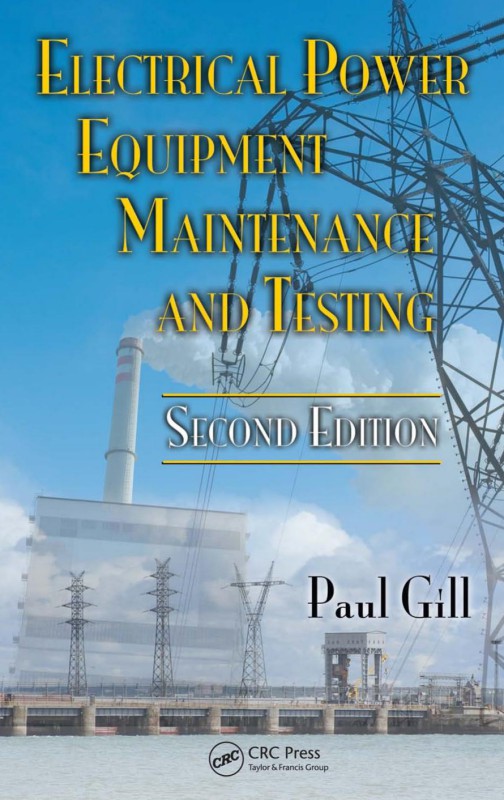
Electrical Power Equipment Maintenance and Testing 2nd Edition by Paul Gill 1574446568 9781574446562
$50.00 Original price was: $50.00.$25.00Current price is: $25.00.
Authors:Paul Gill , Series:Electrical Engineering [88] , Tags:Technology & Engineering; Electrical; Electronics; General , Author sort:Gill, Paul , Ids:9781420017557 , Languages:Languages:eng , Published:Published:Dec 2016 , Publisher:CRC Press , Comments:Comments:The second edition of a bestseller, this definitive text covers all aspects of testing and maintenance of the equipment found in electrical power systems serving industrial, commercial, utility substations, and generating plants. It addresses practical aspects of routing testing and maintenance and presents both the methodologies and engineering basics needed to carry out these tasks. It is an essential reference for engineers and technicians responsible for the operation, maintenance, and testing of power system equipment. Comprehensive coverage includes dielectric theory, dissolved gas analysis, cable fault locating, ground resistance measurements, and power factor, dissipation factor, DC, breaker, and relay testing methods.
Electrical Power Equipment Maintenance and Testing 2nd Edition by Paul Gill – Ebook PDF Instant Download/Delivery. 1574446568, 9781574446562
Full download Electrical Power Equipment Maintenance and Testing 2nd Edition after payment
Product details:
ISBN 10: 1574446568
ISBN 13: 9781574446562
Author: Paul Gill
The second edition of a bestseller, this definitive text covers all aspects of testing and maintenance of the equipment found in electrical power systems serving industrial, commercial, utility substations, and generating plants. It addresses practical aspects of routing testing and maintenance and presents both the methodologies and engineering basics needed to carry out these tasks. It is an essential reference for engineers and technicians responsible for the operation, maintenance, and testing of power system equipment. Comprehensive coverage includes dielectric theory, dissolved gas analysis, cable fault locating, ground resistance measurements, and power factor, dissipation factor, DC, breaker, and relay testing methods.
Electrical Power Equipment Maintenance and Testing 2nd Table of contents:
Chapter 1 Maintenance Strategies, Dielectric Theory, Insulating Materials, Failure Modes, and Maintenance Impact on Arc-Flash Hazards
1.1 Introduction
1.2 Why Maintain and Test
1.3 Overview of Electrical Maintenance and Testing Strategies
1.3.1 Key Factors in EPM Optimization Decisions
1.3.2 General Criteria for an Effective EPM and Testing Program
1.3.3 Qualifications of EPM Personnel
1.3.4 Optimization of PM Intervals
1.3.5 Trending of Test Results
1.3.6 Systematic Failure Analysis Approach
1.3.6.1 Postmaintenance Testing
1.3.6.2 Engineering Support
1.3.6.3 Summary
1.4 Planning an EPM Program
1.4.1 Maintenance Management Considerations
1.4.1.1 Responsibilities
1.4.1.2 Inspection
1.4.1.3 Scheduling
1.4.1.4 Work Orders
1.4.1.5 Record Keeping
1.4.2 Technical Requirements
1.4.2.1 Survey of Plant Equipment
1.4.2.2 Listing of Plant Equipment in the Order of Critical Importance
1.4.2.3 Plan to Perform EPM on Regular Frequency
1.4.2.4 Development of Instruction and Procedures for the EPM Program
1.4.3 What Should Be Included in the EPM Program
1.4.3.1 EPM and Testing
1.4.3.2 Electrical Repairs
1.4.3.3 Analysis of Failures
1.4.3.4 Trending of Maintenance and Testing Data
1.4.3.5 Computerized Maintenance Management System
1.5 Overview of Testing and Test Methods
1.5.1 Types of Tests
1.5.1.1 Acceptance Tests
1.5.1.2 Routine Maintenance Tests
1.5.1.3 Special Maintenance Tests
1.5.2 Types of Testing Methods
1.5.2.1 Solid Insulation Testing
1.5.2.2 Insulating Liquid Testing
1.5.2.3 Protective Device Testing
1.5.2.4 Circuit Breaker Time–Travel Analysis
1.5.2.5 Grounding Electrode Resistance Testing
1.5.2.6 Fault Gas Analysis Testing
1.5.2.7 Infrared Inspection Testing
1.6 Review of Dielectric Theory and Practice
1.6.1 Characteristics of Dielectrics (Insulation)
1.6.1.1 Dielectric Loss
1.6.1.2 PF and DF
1.6.1.3 Capacitance
1.6.2 Insulation as a Capacitor
1.6.3 DC Voltage versus AC Voltage Tests
1.6.3.1 DC Voltage Tests
1.6.3.2 AC Voltage Tests
1.6.4 Insulation Breakdown Modes
1.7 Insulating Materials for Electrical Power Equipment
1.7.1 Rigid Laminates Sheet, Rod, and Tube
1.7.2 Glass Polyester Products
1.7.3 Flexible Laminates and Films
1.7.4 Insulation Temperature Ratings
1.8 Causes of Insulation Degradation and Failure Modes of Electrical Equipment
1.8.1 Failure Modes—Electrical Power Equipment
1.8.1.1 Transformers
1.8.1.2 Switchgear and Circuit Breakers
1.8.1.3 Relays
1.8.1.4 Switchgear Buses
1.8.1.5 Cables and Connectors
1.8.1.6 Rotating Machines
1.9 Maintenance of Protective Devices and their Impact on Arc-Flash Hazard Analysis
1.9.1 Bases of Maintenance and Testing of Protective Devices
1.9.2 Failure Statistics
1.9.3 Flash Hazard Analysis
Chapter 2 Direct-Current Voltage Testing of Electrical Equipment
2.1 Introduction
2.2 DC Voltage Testing of Insulation
2.2.1 Dielectric Phenomena and Polarization
2.2.2 Advantages and Disadvantages of DC Voltage Testing
2.2.2.1 Advantages
2.2.2.2 Disadvantages
2.3 DC Testing Methods
2.3.1 Insulation Resistance Testing
2.3.1.1 Short-Time Readings
2.3.1.2 Time–Resistance Readings
2.3.1.3 PI Test
2.3.1.4 Step-Voltage Readings (DC Voltage Tip-Up Test)
2.3.2 High-Potential Voltage Test
2.4 Transformers
2.4.1 Insulation Resistance Measurement
2.4.2 Dielectric Absorption Test
2.4.3 DC High-Potential Test
2.5 Cables and Accessories
2.5.1 Insulation Resistance Measurement Test
2.5.2 DC Overpotential Testing
2.5.3 Voltage versus Leakage Current Test (Step-Voltage Test)
2.5.4 Leakage Current versus Time Test
2.5.5 Go, No-Go Overpotential Test
2.5.6 DC Overpotential Test Connections and Procedures
2.6 Electrical Switchgear and Circuit Breakers
2.6.1 Insulation Resistance Measurement Test
2.6.2 DC High-Potential Test
2.6.3 Circuit Breaker Contact Resistance Measurement Test
2.7 Motors and Generators
2.7.1 Insulation Resistance Test
2.7.1.1 Field-Winding Test Procedures
2.7.1.2 Overall Stator (Armature Windings) Test
2.7.1.3 Overall System Test for the Motor or Generator
2.7.1.4 Individual Stator Winding Test
2.7.2 DC Overpotential Test
2.7.3 Voltage versus Leakage Current Test (Step-Voltage Test)
2.7.4 Leakage Current versus Time Test
2.8 Lightning Arresters
2.9 Capacitors
2.9.1 Tests to Check the Condition of New Capacitor Units before Placing in Service
2.9.2 Tests to Check the Condition of a Capacitor Unit after It Has Been in Service
2.10 Evaluation of Test Data Readings
2.10.1 Acceptance Criteria for Rating Insulation
2.11 Precautions When Making DC Tests
Chapter 3 Power Factor and Dissipation Factor Testing Methods
3.1 Introduction
3.2 PF and DF Test Methods
3.2.1 General
3.2.2 Principles of PF/DF Testing
3.2.3 Factors That Influence PF Measurements
3.3 Description of the PF Test Equipment
3.3.1 PF and DF Test Set
3.3.2 General Instructions for the Operation of the Megger Test Set
3.3.3 Doble PF Test Set
3.3.4 Operation of Doble PF Test Set
3.4 Basic Test Connections (Test Modes) for PF Testing
3.4.1 Grounded-Specimen Test Mode
3.4.2 GST Mode with Guard (GST-G)
3.4.3 Ungrounded-Specimen Test Mode
3.5 Safety Cautions with PF Testing
3.6 PF Testing of Electrical Apparatus Insulation
3.6.1 Transformers
3.6.1.1 Two-Winding Transformers
3.6.1.2 Three-Winding Transformers
3.6.1.3 Autotransformers
3.6.1.4 PTs
3.6.2 Transformer Bushing
3.6.2.1 Hot-Collar Tests of Noncondenser-Type Bushings
3.6.3 Transformer Excitation Current Test
3.6.4 Transformer Insulating Oils and Fluids
3.6.5 Lightning Arrestors
3.6.6 Circuit Breakers
3.6.6.1 Medium-Voltage Circuit Breakers
3.6.6.2 Oil Circuit Breakers (OCBs)
3.6.7 SF6 Breaker
3.6.8 Rotating Machinery
3.6.8.1 PF Tip-Up Test
3.6.9 Cables and Accessories
3.6.9.1 Shielded or Sheathed Cable
3.6.9.2 Unshielded and Unsheathed Cables
3.6.10 PF Correction Capacitors and Surge Capacitors
3.6.10.1 Bus Insulators
3.6.10.2 Miscellaneous Equipment
3.7 Evaluation and Grading of PF and DF Test Results
3.7.1 General
3.7.2 Analysis of the Results
3.7.2.1 Transformers
3.7.2.2 Bushings
3.7.2.3 Lightning and Surge Arrestors
3.7.2.4 Medium-Voltage Circuit Breakers
3.7.2.5 OCB
3.7.2.6 SF6 Breakers
3.7.2.7 Rotating Machines
3.7.2.8 Cables and Accessories
3.7.2.9 Capacitors
Chapter 4 Insulating Oils, Fluids, and Gases
4.1 Introduction
4.2 Insulating Oil
4.2.1 Deterioration of Insulating Oil
4.2.1.1 Effect of Oxygen on Oil
4.2.1.2 Moisture in Oil
4.2.1.3 Oil Deterioration in Transformers
4.2.1.4 Absorption of Moisture by Insulating Materials
4.2.1.5 Absorption of Nitrogen by Oil
4.2.2 Insulating Oil Testing
4.2.2.1 Dielectric Breakdown Voltage Test (Cup Tests)
4.2.2.2 Acidity Test
4.2.2.3 Interfacial Tension (IFT)
4.2.2.4 Color Test
4.2.2.5 Power Factor Test
4.2.2.6 Specific Gravity
4.2.2.7 Water Content Test (Karl Fisher Method)
4.2.3 Combustible Gas Analysis of Insulating Oil
4.2.3.1 Introduction
4.2.3.2 TCG
4.2.3.3 DGA
4.2.3.4 Comparing the Two Methods
4.2.3.5 Interpretation of Gas Analysis
4.2.3.6 Assessing the Transformer Condition Using the TCGA in the Gas Space
4.2.3.7 Assessing the Transformer Condition Using the DGA Method
4.2.3.8 Fault Types and Associated Key Gases
4.3 Less Flammable Insulating Fluids
4.4 Insulating Liquid Sampling Procedures
4.4.1 Sampling Oil from Transformers
4.4.2 Sampling Oil from Drums or Shipping Containers
4.4.3 Taking Oil Samples for Gas-in-Oil Analysis
4.5 Maintenance and Reconditioning of Insulating Oil and Fluids
4.5.1 Reconditioning Used Insulating Oils
4.5.1.1 Natural Precipitation
4.5.1.2 Filter Presses
4.5.1.3 Filter Press Operation
4.5.1.4 Cartridge Filters
4.5.1.5 Centrifuges
4.5.1.6 Coalescers
4.5.1.7 Vacuum Dehydrators
4.5.2 Maintenance of Less Flammable Fluids
4.5.2.1 Maintenance of RTemp
4.5.2.2 Maintenance of Silicone
4.5.2.3 Maintenance of Wecosol
4.5.2.4 Maintenance of Environtemp (FR3)
4.5.2.5 Maintenance of Askarels
4.6 Insulating Gases
4.6.1 Maintenance of SF6
4.6.1.1 Conducting Particles
4.6.1.2 Moisture
4.6.1.3 Oil Contamination
4.6.1.4 Gaseous Contamination
4.6.1.5 Arc Products
Chapter 5 Transformers
5.1 Introduction
5.2 Transformer Categories and Type
5.2.1 Insulating Medium
5.2.1.1 Dry Type
5.2.1.2 Liquid-Filled Transformer
5.2.2 Construction
5.2.2.1 Tank Construction
5.2.2.2 Core Construction
5.3 Application and Use
5.3.1 Distribution Transformers
5.3.2 Network Transformer
5.3.3 Arc-Furnace Transformer
5.3.4 Rectifier Transformer
5.3.5 Power Transformer
5.4 Transformer Fundamentals
5.4.1 Voltage Relationship
5.4.2 Current Relationship
5.4.3 Impedance Relationship
5.4.4 Summary
5.5 Transformer Polarity, Terminal Markings, and Connections
5.5.1 Single-Phase Transformers
5.5.1.1 Subtractive Polarity
5.5.1.2 Additive Polarity
5.5.2 Three-Phase Transformers
5.6 Transformer Characteristics
5.7 Preventive Maintenance of Transformers
5.7.1 Transformer Installation, Acceptance, and Maintenance
5.7.1.1 Unscheduled Maintenance
5.7.1.2 Ordinary Maintenance
5.7.1.3 Protective Maintenance
5.7.2 Dry-Type Transformers
5.7.2.1 Installation
5.7.2.2 Inspection
5.7.2.3 Acceptance Tests
5.7.2.4 Maintenance
5.7.2.5 Drying-Out Methods
5.7.2.6 Storage
5.7.3 Liquid-Type Transformer
5.7.3.1 Installation
5.7.3.2 Inspection
5.7.3.3 Acceptance Tests
5.7.3.4 Maintenance
5.7.3.5 Drying-Out Methods
5.7.3.6 Storage
5.7.3.7 Transformer Diagnostic Guide
5.8 Transformer Testing
5.8.1 AC Hi-Pot Test
5.8.2 TTR Test
5.8.2.1 Alternative Test for TTR
5.8.2.2 TTR Capacitor
5.8.3 Polarity Test
5.8.4 Induced Potential Test
5.8.5 FRA
5.8.6 DC Winding Resistance
5.8.7 Transformer Core Ground Test
5.8.8 Polarization Recovery Voltage Test
5.8.8.1 The Measuring Instrument
5.8.8.2 Test Setup for Recovery Voltage Measurement on Power Transformers
5.8.8.3 Evaluation of Measured Polarization Spectra
5.9 Online Condition Monitoring of Transformers
5.9.1 Online Monitoring of Transformers
5.10 Online Monitoring of Bushings and Lightning Arrestors
Chapter 6 Cables and Accessories
6.1 Introduction
6.2 Cable Construction and Classification
6.2.1 Types of Conductors
6.2.2 Conductor Arrangement
6.2.3 Cable Types
6.2.4 Insulations
6.2.5 Shielding and Semiconducting Tape
6.2.6 Finishes and Jackets
6.2.7 Cable Construction
6.3 Cable Characteristics
6.4 Electrical Constants
6.5 Cable Ratings
6.6 Cable Selection and Application
6.7 Installation of Cables
6.7.1 Outdoor Installations
6.7.2 Indoor Installations
6.7.3 Bending Data
6.7.4 Pulling Tensions
6.8 Maintenance of Cables
6.9 Cable Failures and Their Analysis
6.10 Field Testing of Medium-Voltage Cables
6.10.1 Cable Degradation and Diagnostic Tests
6.10.2 Safety Practices and Grounding
6.10.3 Cable Testing Methods
6.10.3.1 Insulation Resistance and DC Hi-Pot Testing
6.10.3.2 AC Hi-Pot Testing
6.10.3.3 PF and DF Testing
6.10.3.4 VLF Tests
6.10.3.5 PD Test
6.10.3.6 AC Resonance Test
6.10.3.7 Summary of Testing Methods
6.11 Latest Trends in Cable Condition Monitoring and Aging Assessment
6.11.1 Electronic Characterization and Diagnostic (ECAD®) System
6.11.2 Cable Indentor
6.11.3 Oscillating Wave (OSW) Testing
6.11.4 Broadband Impedance Spectroscopy Prognostic/Diagnostic Technique
6.12 Cable Fault Locating Methods
6.12.1 Terminal Techniques
6.12.2 Tracer Techniques
6.12.3 Application Guide for Cable Fault Locating
Chapter 7 Medium-Voltage Switchgear and Circuit Breakers
7.1 General
7.2 Medium-Voltage Switchgear
7.2.1 Construction Features
7.2.1.1 Metal-Clad Switchgear
7.2.1.2 Metal-Enclosed Interrupter Switchgear
7.2.1.3 Station-Type Cubicle
7.2.2 Short-Circuit Considerations and Power Circuit Breaker Ratings
7.2.3 Selection and Application of Power Circuit Breakers
7.3 Electrical Switchgear Maintenance and Care
7.3.1 MV Switchgear
7.3.1.1 Power Circuit Breakers
7.3.1.2 Maintenance
7.3.2 Air-Magnetic Circuit Breakers
7.3.3 Oil Circuit Breaker
7.3.4 Vacuum Circuit Breaker
7.3.5 Switchgear Enclosure and Bus
7.4 Electrical Switchgear Testing
7.4.1 Insulation Resistance Measurement Test
7.4.2 DC Hi-Pot Test
7.4.3 AC Hi-Pot Test
7.4.4 Power Factor Testing
7.4.5 Circuit Breaker Contact Resistance Measurement Test
7.4.6 Circuit Breaker Time–Travel Analysis
7.4.7 Dynamic Capacitance Measurement of HV Breaker
7.5 Control Power for Switchgear
7.5.1 Control Power Requirements
7.5.1.1 Circuit Breaker Tripping
7.5.1.2 DC Battery Trip
7.5.1.3 Capacitor Trip
7.5.1.4 AC Methods of Tripping
7.5.1.5 Circuit Breaker Closing
7.6 DC (Battery) Control Power Equipment
7.6.1 Sizing
7.6.2 Types of Batteries
7.6.3 Battery Chargers
7.7 AC Control Power Equipment
7.7.1 Sizing
7.7.2 Application
7.8 Maintenance and Care of Batteries for Switchgear Applications
7.8.1 Inspections
7.8.2 Equalizing Charge
7.8.3 Battery Tests
7.8.3.1 Acceptance Test
7.8.3.2 Performance Test
7.8.3.3 Battery Service Test (Load Test)
7.8.3.4 Connection Resistance Test
7.8.3.5 Battery Impedance Test
7.8.4 Addition of Water
7.8.5 Acid Spillage
7.8.6 Loose Connections
7.8.7 Corrosion
7.8.9 Other Maintenance Hints
Chapter 8 Low-Voltage Switchgear and Circuit Breakers
8.1 Low-Voltage Switchgear
8.2 Low-Voltage Circuit Breakers
8.2.1 MCCBs
8.2.2 Insulated-Case Circuit Breakers
8.2.3 Power Circuit Breakers
8.2.4 Fused Power Circuit Breakers
8.3 Overcurrent Protective Devices
8.3.1 Direct-Acting Trip
8.3.2 Static- and Electronic-Trip Units
8.3.3 Monitoring and Protection Packages
8.4 Fuses
8.4.1 Low-Voltage Fuses
8.5 Disconnect Switches
8.5.1 Low-Voltage Switches
8.6 Selection and Application of Low-Voltage Equipment
8.6.1 Assessing Service Life of Low-Voltage Breakers
8.6.1.1 Maximum Voltage Rating or Nominal Voltage Class
8.6.1.2 Continuous Current Rating
8.6.1.3 Rated Short-Circuit Current (Circuit Breakers)
8.6.1.4 Short-Circuit Current Ratings—Panelboards, MCCs, and Switchgear Assemblies
8.6.1.5 Endurance Requirements for Low-Voltage Breakers
8.7 Low-Voltage Switchgear Maintenance and Care
8.7.1 General Guidelines for Inspection and Maintenance of Switchgear
8.7.2 Maintenance of Power Circuit Breakers
8.7.2.1 Mechanical Maintenance Factors
8.7.2.2 Electrical Maintenance Factors
8.7.2.3 Inspections Procedure
8.7.3 MCCBs
8.7.3.1 Mechanical Factors
8.7.3.2 Electrical Factors
8.7.3.3 Inspections Procedure
8.7.4 Switchgear Enclosure
8.7.5 Air Disconnect Switches, Fuses, and Insulators
8.7.5.1 Air Disconnect Switches
8.7.5.2 Power Fuses
8.7.5.3 Insulators
8.8 Maintenance and Testing of Low-Voltage Protective Devices
8.8.1 Power Circuit Breaker Overcurrent Trip Devices
8.8.1.1 Overcurrent Trip Units
8.8.2 Molded-Case Breaker Trips
8.8.2.1 Protective Trip Testing
8.8.2.2 Verification Testing
8.8.3 Overload Relays
8.8.4 Testing of Ground Fault Sensing and Relaying Equipment
8.8.4.1 Preparation for Fielding Training
8.8.4.2 Field Testing
8.9 Uninterruptible Power Supply Commissioning and Testing
8.9.1 Background
8.9.2 Preinstallation Checks and Tests
8.9.3 Combined Test (UPS with the Generator)
8.9.4 Maintenance Test
8.9.4.1 UPS Battery System
8.9.5 Maintenance and Testing
8.9.6 Summary
8.10 Infrared Inspection of Electrical Equipment
8.10.1 Types of Thermographic Scanners
8.10.2 Conducting an IR Thermographic Inspection
8.10.2.1 Delta-T Temperature Rating Systems
8.10.2.2 Standards-Based Temperature Rating System
8.10.3 Conducting a Thermographic Survey
8.10.4 Examples of Thermographic Findings
Chapter 9 Testing and Commissioning of Protective Relays and Instrument Transformers
9.1 Introduction
9.2 Instrument Transformers
9.2.1 Current Transformers
9.2.1.1 CT Accuracy Standards
9.2.1.2 Accuracy Classes for Metering
9.2.1.3 Accuracy Classes for Relaying
9.2.2 Voltage (Potential) Transformers
9.2.3 Polarity of Instrument Transformers
9.2.3.1 Testing for Polarity of Instrument Transformers
9.2.4 Testing for Ratio of Instrument Transformers
9.2.5 Winding and Lead Resistance Measurements
9.2.6 Burden Measurements
9.2.7 CT Remanence
9.2.8 Grounding of CT
9.2.9 Maintenance and Testing of Instrument Transformers
9.3 Protective Relays
9.3.1 Classification of Relays
9.3.2 Overview of Protective Relays—Construction and Types
9.3.2.1 Electromechanical and Induction Relays (First-Generation Relays)
9.3.2.2 Static Relays (Second-Generation Relays)
9.3.2.3 Solid-Sate Relays (Third-Generation Relays)
9.3.2.4 Microprocessor Relays (Fourth-Generation Relays)
9.4 Relay Application and Principles
9.5 Types of Relay Tests
9.6 Testing and Maintenance of Electromechanical Protective Relays
9.6.1 Relay Inspection and Tests
9.6.2 Protective Relay Test Procedures and Circuits
9.6.3 Relay Test Points and Test Circuits
9.6.4 Instrument Transformers Calibration
9.7 Testing and Commissioning of Static and Digital Relays
9.7.1 Test Methods
9.7.2 Commissioning Methods
9.7.3 Commissioning Examples
9.8 Event Reporting
Chapter 10 Motors and Generators
10.1 General
10.2 NEMA Classification of Motors and Generators
10.2.1 According to Size
10.2.2 According to Application
10.2.3 According to Electrical Type
10.2.3.1 AC Motors
10.2.3.2 Polyphase Motor
10.2.3.3 Single-Phase Motor
10.2.3.4 Universal Motor
10.2.3.5 DC Motors
10.2.3.6 DC Generators
10.2.4 According to Physical Protection (Enclosure) and Methods of Cooling
10.2.5 According to Variability of Speed
10.2.6 Terminal Marking of Machines
10.2.6.1 Single-Voltage Motors
10.2.6.2 Dual-Voltage Motors
10.2.6.3 Polyphase Motors
10.3 Applications of Motors and Generators
10.3.1 Electrical Integrity
10.3.1.1 Dielectric Rating
10.3.1.2 Load–Time Rating
10.3.2 Mechanical Integrity
10.4 AC Motors
10.4.1 Environmental Conditions
10.4.2 Direction of Rotation
10.4.3 Operation at Altitudes above 3300 ft
10.4.4 Voltage and Frequency
10.4.5 Horsepower, Torque, and Speed Considerations
10.4.6 Power Factor
10.4.7 Motor Selection
10.5 AC Generators
10.5.1 Service Conditions
10.5.2 Ratings
10.5.3 Temperature Rise
10.5.4 Variation in Voltage
10.5.5 Regulation
10.6 DC Motors
10.6.1 Service Conditions
10.6.2 Operation of DC Motor on Rectified AC
10.6.3 Operation of the DC Motor below Base Speed
10.6.4 Operation of the DC Motor above Base Speed
10.6.5 Overload Capability
10.7 DC Generators
10.7.1 Service Conditions
10.7.2 Ratings
10.7.3 Temperature Rise
10.7.4 Overload Capability
10.7.5 Voltage Excitation
10.7.6 Overspeed
10.8 Motor and Generator Insulation Systems
10.8.1 Machine Insulation System
10.9 Motor and Generator Maintenance
10.9.1 Failure Mechanisms
10.9.1.1 Stator-Winding Insulation
10.9.1.2 Rotor-Winding Insulation
10.9.1.3 Exciter Insulation
10.9.2 General Inspection
10.9.2.1 Visual Inspection
10.9.3 DC Motors and Generators and Repulsion-Induction Motors
10.9.3.1 Cleanliness
10.9.3.2 Armature
10.9.3.4 Field Windings
10.9.4 Induction Motor
10.9.4.1 Stator Windings
10.9.4.2 Air Gap
10.9.4.3 Wound-Rotor Windings
10.9.4.4 Brushes and Rings
10.9.4.5 Centrifugal Switches
10.9.4.6 Squirrel-Cage Rotors
10.9.5 Synchronous Motors and Generators
10.9.6 Cleaning and Varnishing of Machine Windings
10.9.6.1 Cleaning
10.9.6.2 Drying
10.9.6.3 Varnish
10.9.7 Lubrication, Bearings, and Oil Seals
10.9.7.1 Lubrication
10.9.7.2 Sleeve Bearings
10.9.7.3 Antifriction Bearings
10.9.7.4 Installation of Oil Seals
10.9.8 Brushes
10.9.8.1 Brush Adjustment
10.9.9 Balancing
10.9.9.1 Need for Balancing
10.9.9.2 Imbalance Measurement
10.9.10 Belts, Gears, and Pinions
10.9.10.1 Belts
10.9.10.2 Gears and Pinions
10.10 Predictive Maintenance Guide on Motors and Variable Frequency Drives
10.10.1 Power Quality
10.10.2 Power Circuit
10.10.3 Insulation Condition
10.10.4 Stator Condition
10.10.5 Rotor Condition
10.10.6 Air Gap
10.11 Testing of Motors and Generators
10.11.1 Insulation Resistance and Dielectric Absorption Tests
10.11.2 High-Potential Test
10.11.3 PF Test
10.11.4 Dissipation Factor Tan δ Test
10.11.5 Partial Discharge Test
10.11.6 Slot Discharge Test
10.11.7 Conductor Insulation Tests
10.11.8 Motor and Generator Component Tests
10.11.9 Voltage Surge Comparison Test
10.12 Other Insulation Test Methods
10.12.1 Very Low Frequency Testing
10.12.2 Series Resonant Testing
10.13 Vibration Analysis
Chapter 11 Electrical Power System Grounding and Ground Resistance Measurements
11.1 Introduction
11.2 Selection of Grounding Method
11.2.1 Ungrounded Systems
11.2.2 Solidly Grounded Systems
11.2.3 Reactance and Resistance Grounded Systems
11.2.4 Resonant Grounding
11.2.5 Grounding Ungrounded Systems
11.3 Selection of Grounding System
11.3.1 Solidly Grounded System
11.3.2 Low-Resistance Grounding
11.3.3 High-Resistance Grounding
11.3.4 Reactance Grounding
11.3.5 Ground-Fault Neutralizers (Resonant Grounded)
11.4 Understanding Ground Resistance
11.4.1 Grounding Electrode Resistance
11.4.2 Effect of Ground Electrode Size and Depth on Resistance
11.4.3 Effect of Soil Resistivity on Ground Electrode Resistance
11.4.4 Factors Affecting Soil Resistivity
11.4.5 Effect of Ground Electrode Depth on Resistance
11.5 Ground Resistance Values
11.6 Ground Resistance Measurements
11.6.1 Two-Point Method
11.6.2 Three-Point Method
11.6.3 Fall-of-Potential Method
11.6.3.1 Position of the Auxiliary Electrodes on Measurements
11.6.3.2 Measuring Resistance of Ground Electrodes (62% Method)
11.6.3.3 Auxiliary Electrode Spacing
11.6.3.4 Multiple Electrode System
11.6.4 Ratio Method
11.6.5 Soil Resistivity Measurements (Four-Point Measurement)
11.6.6 Touch Potential Measurements
11.6.7 Clamp-On Ground Resistance Measurement
11.6.7.1 Principle of Operation
11.6.7.2 In-Field Measurement
11.6.7.3 Transmission Towers
11.6.7.4 Central Office Locations
11.7 Ground Grid Integrity Measurements
Chapter 12 Power Quality, Harmonics, and Predictive Maintenance
12.1 Background
12.2 PQ Concept and Fundamentals
12.2.1 Types and Consequences of Electrical Disturbances
12.3 Origins of PQ Problems and Harmonics
12.4 Characteristics of Typical Linear and Nonlinear Loads
12.4.1 Voltage and Current Characteristics of Nonlinear Loads
12.4.1.1 HD Terminology
12.4.1.2 Types of Nonlinear Loads
12.4.1.3 PF Characteristics of Loads
12.4.1.4 Phase Sequence of Harmonics
12.4.1.5 Harmonic Generating Characteristics
12.4.1.6 Sensitivity to Harmonics
12.4.1.7 Sensitivity to Voltage Variation
12.4.1.8 Sensitivity to Voltage Flicker
12.4.1.9 Sensitivity to Noise
12.5 Effects of Harmonic on Power System Equipment and Loads
12.5.1 Basic Concepts on Effects of Harmonics
12.5.1.1 Thermal Stress
12.5.1.2 Insulation Stress
12.5.1.3 Load Disruption
12.5.2 Harmonic Effects on Power System Equipment
12.5.2.1 Transformers
12.5.2.2 Rotating Machines
12.5.2.3 Capacitor Banks
12.5.2.4 Switchgear
12.5.2.5 Protective Relays
12.5.2.6 Metering Devices
12.5.2.7 Electronic Equipment
12.5.2.8 Lighting Devices
12.6 Predictive Maintenance and PQ Measurements
12.6.1 Introduction
12.6.2 Safety Standards for Test Instruments
12.6.2.1 Test Instrument Standards
12.6.2.2 Instruments for PQ Measurements
12.6.3 PQ Measurement Guidelines
12.6.3.1 Preparation for Conducting Measurements
12.6.3.2 Basic Power Measurements
12.6.3.3 Measurements at the Receptacle of a Branch Circuit
12.6.3.4 Measurement at the Service Panel
12.6.3.5 Measurements at the Transformer
12.6.3.6 Electrical Noise
12.6.3.7 Transients
12.6.3.8 Lightning
12.6.3.9 Polyphase Induction Motors
12.6.3.10 PQ Measurements of VFDs
12.6.3.11 Power System Resonance
12.6.3.12 Commercial Lighting Load
12.6.3.13 Summary of PQ Problems
12.7 PQ Solution and Power Treatment Devices
12.7.1 Voltage Disturbances and Noise
12.7.1.1 Noise Filters (Electronic Filters)
12.7.1.2 TVSS
12.7.1.3 Voltage Regulators
12.7.1.4 Isolation Transformers
12.7.1.5 Power Conditioners
12.7.1.6 UPS
12.7.2 HDs
12.7.2.1 Industry Standards on Limits of Harmonics
12.7.2.2 Evaluating System Harmonics
12.7.2.3 Harmonic Solutions—Mitigation Devices and Methods
12.7.3 Wiring and Grounding Problems
Chapter 13 Electrical Safety, Arc-Flash Hazard, Switching Practices, and Precautions
13.1 Introduction
13.2 Industry Standards and Regulatory Requirements for Safety
13.2.1 ANSI C2: The National Electrical Safety Code-2007
13.2.2 ANSI/National Fire Protection Association (NFPA) 70, National Electrical Code (NEC)-2008
13.2.3 ANSI/NFPA 70B, Standard for Electrical Equipment Maintenance-2006
13.2.4 ANSI/NFPA 70E, Standard for Electrical Safety in the Workplace-2004
13.2.5 Occupational Safety and Health Administration (OSHA) Standards
13.3 Arc-Flash Hazard and Regulatory Requirements
13.3.1 Summary of NFPA 70, 70E, and OSHA Requirements
13.3.2 Overview of Arc-Flash Hazard
13.3.3 Arc-Flash Analysis
13.4 Electrical Safety Practices and Precautions
13.4.1 Electrical Safety
13.4.2 “On-Site” Electrical Safety
13.4.3 “On-Site” Safety Kit
13.4.4 Work Area Control
13.4.5 Lock-Out and/or Tagging
13.4.6 Protective Apparel-Operating Electrical Equipment
13.4.7 Testing of Electrical Circuits and/or Equipment
13.4.8 Rubber Gloves for Electrical Work-Use and Care
13.4.9 Low-Voltage Tester
13.4.10 Medium- and HV-Detectors
13.4.11 Grounds-Personnel Protection
13.5 Electrical Switching Practices and Precautions
13.5.1 On-Site Circuit Breaker Maintenance Safety Checklists
13.5.2 Confined Spaces—Procedure for Entering
13.5.3 Electrical Precautions
13.5.3.1 General Precautions
13.5.3.2 Loads and Currents
13.5.3.3 Switch Sticks
13.5.3.4 Opening Disconnects by Using the “Inching” Method
13.5.3.5 Selector Disconnects
13.5.3.6 Circuit Breaker Disconnects
13.5.3.7 Interrupter Switches
13.5.3.8 Closing Disconnects under Load Conditions
13.5.3.9 Air Break Switches
13.5.3.10 Protection against Air Break Flashover
13.5.3.11 Motor-Controlled Disconnects and Air Breaks
13.6 Electrical Fire Emergencies
13.6.1 Never Make Direct Contact with Any Energized Object
13.6.2 Stay Clear of Vicinity of Any Faulty Energized Object
13.6.3 Be Alert in Vicinity of Any Energized Object
13.6.3.1 Beware of Covered Wires
13.6.3.2 Beware of Telephone Cables
13.6.4 Assume Every Fallen Wire Is Energized and Dangerous
13.6.4.1 Wire on Ground
13.6.4.2 Wire on Object
13.6.4.3 Wire on Vehicle
13.6.5 Never Cut Wires Except to Protect Life
13.6.5.1 Take Care after Cutting
13.6.5.2 Cutting Service Wires
13.6.6 Use Approved Procedures and Equipment If You Must Work Near Energized Facilities
13.6.7 Avoid Using Hose Streams on Energized Facilities
13.6.8 Be Equally Alert Indoors and Outdoors
13.6.9 Protect People and Property in Surrounding Area and Do Not Fight Fires on Electric Equipment Until an Electric Company Representative Arrives
13.6.10 Hose Streams May Be More Hazardous than Helpful Until Any Underground Fault Is De-Energized
13.7 Effects of Electrical Shock
13.8 First Aid
13.8.1 Shock
13.8.2 Resuscitation
13.8.3 Resuscitation—Mouth-to-Mouth (Nose) Method
13.8.4 Important Points to Remember
13.8.5 Two-Victim Method of Resuscitation—Mouth-to Mouth (Nose)
13.8.6 External Heart Compression
People also search for Electrical Power Equipment Maintenance and Testing 2nd:
electrical maintenance requirements
types of maintenance in electrical system
what is electrical maintenance
electrical maintenance engineer responsibilities in power plant

