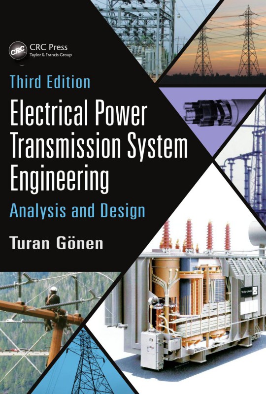
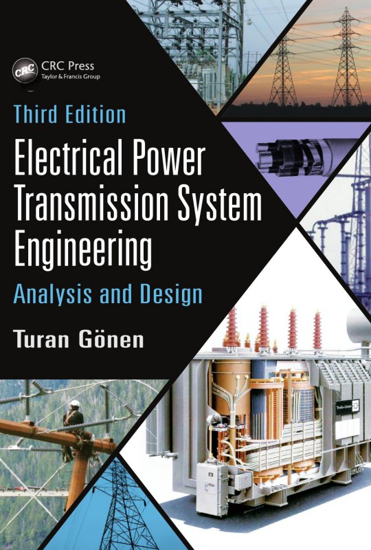
(Ebook PDF) Electrical Power Transmission System Engineering Analysis and Design 2nd Edition by Turan Gonen 1482232243 9781482232240 full chapters
$50.00 Original price was: $50.00.$25.00Current price is: $25.00.
Authors:Turan Gonen , Series:Electrical Engineering [228] , Tags:Technology & Engineering; Electronics; General; Power Resources; Electrical , Author sort:Gonen, Turan , Ids:Google; 9781439802540 , Languages:Languages:eng , Published:Published:May 2009 , Publisher:Taylor & Francis , Comments:Comments:Although many textbooks deal with a broad range of topics in the power system area of electrical engineering, few are written specifically for an in-depth study of modern electric power transmission. Drawing from the author’s 31 years of teaching and power industry experience, in the U.S. and abroad, Electrical Power Transmission System Engineering: Analysis and Design, Second Edition provides a wide-ranging exploration of modern power transmission engineering. This self-contained text includes ample numerical examples and problems, and makes a special effort to familiarize readers with vocabulary and symbols used in the industry. Provides essential impedance tables and templates for placing and locating structures Divided into two sections—electrical and mechanical design and analysis—this book covers a broad spectrum of topics. These range from transmission system planning and in-depth analysis of balanced and unbalanced faults, to construction of overhead lines and factors affecting transmission line route selection. The text includes three new chapters and numerous additional sections dealing with new topics, and it also reviews methods for allocating transmission line fixed charges among joint users. Uniquely comprehensive, and written as a self-tutorial for practicing engineers or students, this book covers electrical and mechanical design with equal detail. It supplies everything required for a solid understanding of transmission system engineering.
Electrical Power Transmission System Engineering: Analysis and Design 2nd Edition by Turan Gonen – Ebook PDF Instant Download/DeliveryISBN: 1482232243, 9781482232240
Full download Electrical Power Transmission System Engineering: Analysis and Design 2nd Edition after payment.
Product details:
ISBN-10 : 1482232243
ISBN-13 : 9781482232240
Author : Turan Gonen
Electrical Power Transmission System Engineering: Analysis and Design is devoted to the exploration and explanation of modern power transmission engineering theory and practice. Designed for senior-level undergraduate and beginning-level graduate students, the book serves as a text for a two-semester course or, by judicious selection, the material
Electrical Power Transmission System Engineering: Analysis and Design 2nd Table of contents:
SECTION I Electrical Design and Analysis
1 Transmission System Planning
1.1 INTRODUCTION
1.2 AGING TRANSMISSION SYSTEM
TABLE 1.1 Standard System Voltages
FIGURE 1.1 A three-phase double-circuit transmission line made of steel towers.
FIGURE 1.2 A three-phase double-circuit transmission line made of steel towers.
FIGURE 1.3 Installation of a 345 kV double-circuit transmission tower made of steel cage.
FIGURE 1.4 A transmission line is being upgraded.
FIGURE 1.5 Historical trends in technology and cost of electrical energy of the past until year 1980.
TABLE 1.2 Actual and Planned Transmission Investment by Privately Owned Integrated and Stand-Alone Transmission Companies
1.3 BENEFITS OF TRANSMISSION
TABLE 1.3 1980 Regional Transmission Lines in Miles
1.4 POWER POOLS
1.5 TRANSMISSION PLANNING
1.6 TRADITIONAL TRANSMISSION SYSTEM PLANNING TECHNIQUES
FIGURE 1.6 Block diagram of typical transmission system planning process.
FIGURE 1.7 Logic diagram for transmission expansion study.
1.7 MODELS USED IN TRANSMISSION SYSTEM PLANNING
1.8 TRANSMISSION ROUTE IDENTIFICATION AND SELECTION
FIGURE 1.8 Transmission route selection procedure.
1.9 TRADITIONAL TRANSMISSION SYSTEM EXPANSION PLANNING
1.9.1 Heuristic Models
1.9.2 Single-Stage Optimization Models
1.9.2.1 Linear Programming
1.9.2.2 Integer Programming
1.9.2.3 Gradient Search Method
1.9.3 Time-Phased Optimization Models
1.10 TRADITIONAL CONCERNS FOR TRANSMISSION SYSTEM PLANNING*
1.10.1 Planning Tools
1.10.2 Systems Approach
FIGURE 1.9 Schematic view of transmission planning system.
1.10.3 Database Concept
FIGURE 1.10 Block diagram of future transmission-system-planning process.
1.11 NEW TECHNICAL CHALLENGES
1.12 TRANSMISSION PLANNING AFTER OPEN ACCESS
1.13 POSSIBLE FUTURE ACTIONS BY THE FERC
REFERENCES
GENERAL REFERENCES
2 Transmission Line Structures and Equipment
2.1 INTRODUCTION
2.2 DECISION PROCESS TO BUILD A TRANSMISSION LINE
FIGURE 2.1 Critical path steps in an EHV line design.
TABLE 2.1 Line Design Characteristics Affecting Cost
2.3 DESIGN TRADE-OFFS
2.4 TRADITIONAL LINE DESIGN PRACTICE
2.4.1 Factors Affecting Structure-Type Selection
2.4.2 Improved Design Approaches
FIGURE 2.2 The methodology involved in developing improved design criteria of OH transmission lines based on reliability concepts.
2.5 TRANSMISSION LINE STRUCTURES
2.5.1 Compact Transmission Lines
FIGURE 2.3 Typical compact configurations (not to scale): (a) horizontal unshielded, (b) horizontal shielded, (c) vertical, (d) delta, and (e) vertical delta.
FIGURE 2.4 A double-circuit 138 kV line built by using steel poles, having two 138 kV top circuits and a 34.5 kV single circuit underbuilt.
FIGURE 2.5 A double-circuit 138 kV line built by using steel poles, having two 138 kV top circuits and a 34.5 kV single circuit underbuilt. (Union Electric Company.)
FIGURE 2.6 A double-circuit 138 kV line built by using steel poles, having two 138 kV circuits underbuilt. (Union Electric Company.)
2.5.2 Conventional Transmission Lines
2.5.3 Design of Line Support Structures
FIGURE 2.7 A typical 345 kV transmission line with single-circuit and wood H-frame. (Union Electric Company.)
FIGURE 2.8 A typical 345 kV transmission line with bundled conductors and double circuit on steel towers. (Union Electric Company.)
FIGURE 2.9 A typical 345 kV transmission line with bundled conductors and double circuit on steel towers. (Union Electric Company.)
FIGURE 2.10 Typical pole- and lattice-type structures for 345 kV transmission systems.
FIGURE 2.11 Typical wood H-frame-type structures for 345 kV transmission systems.
2.6 SUBTRANSMISSION LINES
FIGURE 2.12 Typical pole- and lattice-type structures for 500 kV transmission systems.
FIGURE 2.13 Typical pole- and lattice-type structures for 735-800 kV transmission systems.
FIGURE 2.14 A typical 230 kV transmission line steel tower with bundled conductors and double circuit.
FIGURE 2.15 A lineman working from a helicopter platform.
FIGURE 2.16 Two 345 and 230 kV transmission lines side by side.
FIGURE 2.17 A 345 kV transmission line and a 230 kV transmission line side by side.
FIGURE 2.18 A 230/161 kV substation with a 230 kV transmission line passing by.
FIGURE 2.19 A 115 kV transmission line and a 230 kV transmission line side by side.
FIGURE 2.20 A cluster of four transmission lines side by side.
FIGURE 2.21 A 115 kV transmission line and a 345 kV transmission line with corner towers.
FIGURE 2.22 A 345 kV transmission line and a 115 kV transmission line side by side.
FIGURE 2.23 A 230 kV switchyard.
FIGURE 2.24 A pole-top view.
FIGURE 2.25 A 230/34.5 kV switchyard.
2.6.1 Subtransmission Line Costs
FIGURE 2.26 A galvanized dead-end corner pole of a 230 kV transmission line.
FIGURE 2.27 A substation connection of transmission lines.
FIGURE 2.28 A radial-type subtransmission.
FIGURE 2.29 An improved form of radial-type subtransmission.
FIGURE 2.30 A loop-type subtransmission.
FIGURE 2.31 A grid- or network-type subtransmission.
FIGURE 2.32 A typical 34.5 kV line with a double circuit and wood poles. It has a newer style construction. (Union Electric Company.)
FIGURE 2.33 A 34.5 kV line with a single circuit and wood poles. It also has a 12.47 kV underbuilt line and 34.5 kV switch. It has an old style construction. (Union Electric Company.)
FIGURE 2.34 A typical 34.5 kV line with a double circuit and wood poles. It also has a 4.16 kV underbuilt line and a 34.5 kV switch. (Union Electric Company.)
FIGURE 2.35 A typical 12.47 kV line with a single circuit and wood pole. It has a newer type of pole-top construction. (Union Electric Company.)
2.7 TRANSMISSION SUBSTATIONS
2.7.1 Additional Substation Design Considerations
FIGURE 2.36 Establishment of a new substation.
FIGURE 2.37 A bulk power substation operating at 138/34.5 kV voltage level. (Union Electric Company.)
FIGURE 2.38 A distribution substation operating at 34.5/12.47 kV voltage level. (Union Electric Company.)
FIGURE 2.39 A distribution substation operating at 34.5/4.16 kV voltage level. (Union Electric Company.)
2.7.2 Substation Components
2.7.3 Bus and Switching Configurations
FIGURE 2.40 Most commonly used substation bus schemes: (a) single-bus scheme, (b) double-bus–double-breaker scheme, and (c) main-and-transfer bus scheme.
2.7.4 Substation Buses
FIGURE 2.41 Most commonly used substation bus schemes: (a) double-bus–single-breaker scheme, (b) ring bus scheme, and (c) breaker-and-a-half scheme.
TABLE 2.2 Summary of Comparison of Switching Schemes
2.7.4.1 Open-Bus Scheme
FIGURE 2.42 A low-profile EHV substation using inverted breaker-and-a-half scheme.
2.7.4.2 Inverted-Bus Scheme
2.8 SF6-INSULATED SUBSTATIONS
2.9 TRANSMISSION LINE CONDUCTORS
2.9.1 Conductor Considerations
2.9.2 Conductor Types
2.9.3 Conductor Size
2.9.3.1 Voltage Drop Considerations
TABLE 2.3 Standard Conductor Sizes
2.9.3.2 Thermal Capacity Considerations
2.9.3.3 Economic Considerations
2.9.4 Overhead Ground Wires
2.9.5 Conductor Tension
2.10 INSULATORS
2.10.1 Types of Insulators
FIGURE 2.43 Typical (side) post-type insulators used in (a) 69 kV and (b) 138 kV.
FIGURE 2.44 Devices used to protect insulator strings: (a) suspension string with arcing horns, (b) suspension string with grading shields (or arcing rings), and (c) suspension string with control ring.
2.10.2 Testing of Insulators
2.10.3 Voltage Distribution over a String of Suspension Insulators
TABLE 2.4 Flashover Characteristics of Suspension Insulator Strings and Air Gaps
FIGURE 2.45 Voltage distribution along the surface of single clean cap-and-pin suspension insulator.
FIGURE 2.46 A typical voltage distribution on surfaces of three clean cap-and-pin suspension insulator units in series.
FIGURE 2.47 Voltage distribution among suspension insulator units.
FIGURE 2.48 An equivalent circuit for voltage distribution along clean eight-unit insulator string.
FIGURE 2.49 Voltage distribution along a clean eight-unit cap-and-pin insulator string.
2.10.4 Insulator Flashover due to Contamination
TABLE 2.5 Numbers of Flashovers Caused by Various Contaminant, Weather, and Atmospheric Conditions
FIGURE 2.50 Changes in channel position of contaminated flashover.
2.10.5 Insulator Flashover on Overhead HVDC Lines
2.11 SUBSTATION GROUNDING
2.11.1 Electrical Shock and Its Effects on Humans
TABLE 2.6 Effect of Electric Current (in mA) on Men and Women
FIGURE 2.51 Typical electrical shock hazard situations: (a) touch potential, (b) its equivalent circuit, (c) step potential, and (d) its equivalent circuit.
FIGURE 2.52 Possible basic shock situations.
2.11.2 Reduction of Factor Cs
FIGURE 2.53 Surface layer derating factor Cs versus thickness of surface material in meters.
Example 2.1
Example 2.2
TABLE 2.7 Resistivity of Different Soils
2.11.3 Ground Resistance
TABLE 2.8 Effect of Moisture Content on Soil Resistivity
FIGURE 2.54 Resistance of earth surrounding an electrode.
FIGURE 2.55 Variation of soil resistivity with depth for soil having uniform moisture content at all depths.
FIGURE 2.56 Approximate ground resistivity distribution in the United States. Notes: All figures on this map indicate ground resistivity (Rho) in ohm-meters. These data are taken from FCC figure M3, February 1954. The FCC data indicate ground conductivity in milliohms per meter. Resistivities of special note from Transmission Line Reference Book by EPRI in ohmmeters: Swampy ground (10-100), pure slate (10,000,000), and sandstone (100,000,000).
TABLE 2.9 Material Constants of the Typical Grounding Material Used
2.11.4 Soil Resistivity Measurements
2.11.4.1 Wenner Four-Pin Method
FIGURE 2.57 Wenner four-pin method.
2.11.4.2 Three-Pin or Driven-Ground Rod Method
FIGURE 2.58 Circuit diagram for three-pin or driven-ground rod method.
2.12 SUBSTATION GROUNDING
FIGURE 2.59 The relationship between asymmetrical fault current, dc decaying component, and symmetrical fault current.
2.13 GROUND CONDUCTOR SIZING FACTORS
2.14 MESH VOLTAGE DESIGN CALCULATIONS
FIGURE 2.60 The effect of the spacing (D) between conductors on Km.
FIGURE 2.61 The effect of the number of conductors (n) on the Km.
FIGURE 2.62 The relationship between the diameter of the conductor (d) and the Km.
FIGURE 2.63 The relationship between the depth of the conductor (h) and Km.
2.15 STEP VOLTAGE DESIGN CALCULATIONS
FIGURE 2.64 The relationship between the distance (D) between the conductors and the geometric factor Ks.
FIGURE 2.65 The relationship between the number of conductors (n) and the geometric factor Ks.
FIGURE 2.66 The relationship between the depth of grid conductors (h) in meter and the geometric factor Ks.
2.16 TYPES OF GROUND FAULTS
2.16.1 Line-to-Line-to-Ground Fault
2.16.2 Single Line-to-Ground Fault
2.17 GROUND POTENTIAL RISE
FIGURE 2.67 The effects of number of grid conductors (n), without ground rods, on the ground grid resistance.
FIGURE 2.68 The effects of varying the depth of burial of the grid (h) from 0.5 to 2.5 m and the number of conductors from 4 to 10.
Example 2.3
FIGURE 2.69 Substation grounding design procedure block diagram.
TABLE 2.10 Initial Design Parameters
FIGURE 2.70 Preliminary design.
TABLE 2.11 Approximate Equivalent Impedance of Transmission Line OH Shield Wires and Distribution Feeder Neutrals
2.18 TRANSMISSION LINE GROUNDS
FIGURE 2.71 Two basic types of counterpoises: (a) continuous (parallel) and (b) radial.
2.19 TYPES OF GROUNDING
FIGURE 2.72 Grounding transformers used in delta-connected systems: (a) using wye–delta-connected small distribution transformers or (b) using grounding autotransformers with interconnected wye or zigzag windings.
2.20 TRANSFORMER CLASSIFICATIONS
FIGURE 2.73 A 40 MVA, 110 kV ± 16%/21 kV, three-phase, core-type transformer, 5.2 m high, 9.4 m long, 3 m wide, weighing 80 tons.
FIGURE 2.74 A 850/950/1100 MVA, 415 kV ± 11%/27 kV, three-phase, shell-type transformer, 11.3 high, 14 long, 5.7 wide, weighing (without cooling oil) 552 tons.
FIGURE 2.75 The 10 MVA and 50 kVA, core-type three-phase transformers with GEAFOL solid dielectric cores.
FIGURE 2.76 A typical core and coil assembly of a three-phase, core-type, power transformer.
FIGURE 2.77 The 10MVA and 50 kVA, core-type three-phase transformers with GEAFOL solid dielectric cores.
FIGURE 2.78 A core-type three-phase transformer with GEAFOL solid dielectric core.
TABLE 2.12 Equivalent Cooling Classes
2.20.1 Transformer Connections
FIGURE 2.79 Possible three-phase transformer connections.
2.20.2 Transformer Selection
2.21 ENVIRONMENTAL IMPACT OF TRANSMISSION LINES
2.21.1 Environmental Effects
2.21.2 Biological Effects of Electric Fields
TABLE 2.13 Russian Rules for Duration of Work in Live Substations
2.21.3 Biological Effects of Magnetic Fields
2.21.4 Magnetic Field Calculation
FIGURE 2.80 Magnetic field generation by a current-carrying conductor.
FIGURE 2.81 Magnetic field density distribution.
Example 2.4
FIGURE 2.82 A typical tower used in Example 2.4.
FIGURE 2.83 The radiuses in question in terms of the geometry involved with respect to the edge of the ROW.
FIGURE 2.84 The radiuses in question in terms of the geometry involved with respect to the center of the ROW.
2.22 HIGH-VOLTAGE BUSHINGS WITH DRAW LEADS AND THEIR FAILURES
REFERENCES
3 Flexible AC Transmission System (FACTS) and Other Concepts
3.1 INTRODUCTION
3.2 FACTORS AFFECTING TRANSMISSION GROWTH
3.3 STABILITY CONSIDERATIONS
3.4 POWER TRANSMISSION CAPABILITY OF A TRANSMISSION LINE
3.5 SURGE IMPEDANCE AND SURGE IMPEDANCE LOADING OF A TRANSMISSION LINE
TABLE 3.1 SIL Capability
Example 3.1
3.6 LOADABILITY CURVES
FIGURE 3.1 Illustration of the power system model used for the transmission line loadability curves.
FIGURE 3.2 Transmission line loadability curves for EHV and UHV lines.
3.7 COMPENSATION
FIGURE 3.3 Cost of power versus loading of the line.
FIGURE 3.4 A transmission system with both series and shunt compensation.
3.8 SHUNT COMPENSATION
3.8.1 Effects of Shunt Compensation on Transmission Line Loadability
FIGURE 3.5 The effects of having only shunt reactor compensation on the line loadability.
3.8.2 Shunt Reactors and Shunt Capacitor Banks
3.9 SERIES COMPENSATION
3.9.1 Effects of Series Compensation on Transmission Line Loadability
FIGURE 3.6 Effects of having only series compensation on the line loadability.
FIGURE 3.7 Effects of system impedance on line loadability without having any series or shunt compensation.
FIGURE 3.8 Power flow through a transmission line.
3.9.2 Series Capacitors
FIGURE 3.9 A simplified schematic diagram of an SC segment.
FIGURE 3.10 Schematic of typical SC compensation equipment.
Example 3.2
Example 3.3
3.10 FLEXIBLE AC TRANSMISSION SYSTEMS
FIGURE 3.11 (a) An uncompensated transmission line and (b) its voltage-phasor diagram.
FIGURE 3.12 (a) A transmission line with series compensation and (b) its voltage-phasor diagram.
FIGURE 3.13 (a) A transmission line with shunt compensation and (b) its voltage-phasor diagram.
3.11 STATIC VAR CONTROL
FIGURE 3.14 Principles of SVC compensation: (a) TCR and (b) TSC.
FIGURE 3.15 Schematic representation of three types of SVCs: (a) TCR with FC bank, (b) TCR with switched capacitor banks, and (c) TSC compensator.
FIGURE 3.16 Reactive power variation of TCR with switched capacitor banks.
3.12 STATIC VAR SYSTEMS
3.13 THYRISTOR-CONTROLLED SERIES COMPENSATOR
FIGURE 3.17 Schematic diagram of a typical static var system (as indicated by the dash signs).
FIGURE 3.18 One-line diagram of a TCSC installed at a substation.
3.14 STATIC COMPENSATOR
FIGURE 3.19 An illustration of the operation principle of STATCOM (or advanced SVC).
FIGURE 3.20 A thyristor-controlled braking resistor.
3.15 THYRISTOR-CONTROLLED BRAKING RESISTOR
3.16 SUPERCONDUCTING MAGNETIC ENERGY SYSTEMS
3.17 SUBSYNCHRONOUS RESONANCE
FIGURE 3.21 SMES unit with double GTO thyristor bridge.
3.18 USE OF STATIC COMPENSATION TO PREVENT VOLTAGE COLLAPSE OR INSTABILITY
3.19 ENERGY MANAGEMENT SYSTEM
FIGURE 3.22 Monitoring and controlling an electric power system.
3.20 SUPERVISORY CONTROL AND DATA ACQUISITION
FIGURE 3.23 SCADA.
3.21 ADVANCED SCADA CONCEPTS
FIGURE 3.24 SCADA in virtual system established by WAN.
3.22 SUBSTATION CONTROLLERS
FIGURE 3.25 Substation controller.
3.23 SIX-PHASE TRANSMISSION LINES
FIGURE 3.26 Polyphase phasor systems: (a) three-phase system and (b) six-phase system.
FIGURE 3.27 Comparative tower heights for a double-circuit (a) three-phase transmission line versus (b) a six-phase transmission line.
FIGURE 3.28 Six-phase transformer bank made up of two three-phase transformers connected as (a) delta–wye and delta-inverted wye and (b) wye–wye and wye-inverted wye.
REFERENCES
4 Overhead Power Transmission
4.1 INTRODUCTION
4.2 REVIEW OF BASICS
4.2.1 Complex Power in Balanced Transmission Lines
FIGURE 4.1 Per-phase representation of short transmission line: (a) a short transmission line and (b) voltage phasor diagram.
Example 4.1
4.2.2 One-Line Diagram
FIGURE 4.2 Power system representations: (a) one-line diagram, (b) three-phase equivalent impedance diagram, and (c) equivalent impedance diagram per phase.
TABLE 4.1 Symbols Used in One-Line Diagrams
4.2.3 Per-Unit System
4.2.3.1 Single-Phase System
4.2.3.2 Converting from Per-Unit Values to Physical Values
4.2.3.3 Change of Base
4.2.4 Three-Phase Systems
FIGURE 4.3 Conventional three-phase transformer connections: (a) wye–wye connection, (b) delta–delta connection, (c) wye–delta connection, and (d) delta–wye connection.
Example 4.2
Example 4.3
Example 4.4
FIGURE 4.4 The one-line diagram for Example 4.4.
TABLE 4.2 Results of Example 4.4
4.2.5 Constant-Impedance Representation of Loads
FIGURE 4.5 Load representations as (a) real and reactive powers, (b) constant impedance in terms of series combination, and (c) constant impedance in terms of parallel combination.
4.3 THREE-WINDING TRANSFORMERS
FIGURE 4.6 A single-phase three-winding transformer: (a) winding diagram and (b) equivalent circuit.
4.4 AUTOTRANSFORMERS
FIGURE 4.7 Schematic diagram of ideal (step-down) transformer connected as (a) two-winding transformer and (b) autotransformer.
4.5 DELTA–WYE AND WYE–DELTA TRANSFORMATIONS
FIGURE 4.8 Delta-to-wye or wye-to-delta transformations.
4.6 TRANSMISSION-LINE CONSTANTS
4.7 RESISTANCE
4.8 INDUCTANCE AND INDUCTIVE REACTANCE
4.8.1 Single-Phase Overhead Lines
FIGURE 4.9 Magnetic field of single-phase line.
4.8.2 Three-Phase Overhead Lines
FIGURE 4.10 A complete transposition cycle of three-phase line.
4.9 CAPACITANCE AND CAPACITIVE REACTANCE
4.9.1 Single-Phase Overhead Lines
FIGURE 4.11 Capacitance of single-phase line.
FIGURE 4.12 Line-to-line capacitance.
FIGURE 4.13 Line-to-neutral capacitance.
4.9.2 Three-Phase Overhead Lines
FIGURE 4.14 Three-phase line with equilateral spacing.
4.10 TABLES OF LINE CONSTANTS
Example 4.5
Example 4.6
Example 4.7
4.11 EQUIVALENT CIRCUITS FOR TRANSMISSION LINES
4.12 SHORT TRANSMISSION LINES (UP TO 50 mi, OR 80 km)
FIGURE 4.15 Distributed constant equivalent circuit of line.
FIGURE 4.16 Equivalent circuit of short transmission line.
FIGURE 4.17 Phasor diagram of short transmission line to inductive load.
FIGURE 4.18 Phasor diagram of short transmission line connected to capacitive load.
4.12.1 Steady-State Power Limit
4.12.2 Percent Voltage Regulation
Example 4.8
Example 4.9
4.12.3 Representation of Mutual Impedance of Short Lines
FIGURE 4.19 Representation of mutual impedance: (a) between two circuits and (b) its equivalent circuit.
FIGURE 4.20 Representation of mutual impedance between two circuits by means of 1:1 transformer.
FIGURE 4.21 Resultant equivalent circuit.
Example 4.10
4.13 MEDIUM-LENGTH TRANSMISSION LINES (UP TO 150 mi, OR 240 km)
FIGURE 4.22 Nominal-T circuit: (a) actual circuit and (b) its equivalent lumped circuit.
FIGURE 4.23 Nominal-π circuit: (a) actual circuit and (b) its equivalent lumped circuit.
Example 4.11
Example 4.12
4.14 LONG TRANSMISSION LINES (ABOVE 150 mi, OR 240 km)
FIGURE 4.24 One phase and neutral connection of three-phase transmission line.
Example 4.13
4.14.1 Equivalent Circuit of Long Transmission Line
FIGURE 4.25 Equivalent-π and equivalent-T circuits for a long transmission line: (a) equivalent-π circuit and (b) equivalent-T circuit.
Example 4.14
FIGURE 4.26 Equivalent-π circuit.
FIGURE 4.27 Nominal-π circuit.
FIGURE 4.28 The T circuits: (a) equivalent T and (b) nominal T.
4.14.2 Incident and Reflected Voltages of Long Transmission Line
Example 4.15
4.14.3 Surge Impedance Loading of Transmission Line
FIGURE 4.29 Transmission-line compensation by adding lump inductances in (a) series and (b) parallel (i.e., shunt).
FIGURE 4.30 Transmission-line compensation by adding capacitances in (a) parallel (i.e., shunt) and (b) series.
Example 4.16
4.15 GENERAL CIRCUIT CONSTANTS
4.15.1 Determination of A, B, C, and D Constants
FIGURE 4.31 General two-port, four-terminal network.
4.15.2 A, B, C, and D Constants of Transformer
TABLE 4.3 General Circuit Contents for Different Network Types
TABLE 4.4 Network Conversion Formulas
FIGURE 4.32 Transformer equivalent circuit at no load.
FIGURE 4.33 Transformer equivalent circuit at full load.
4.15.3 Asymmetrical π and T Networks
FIGURE 4.34 Asymmetrical-π network.
FIGURE 4.35 Asymmetrical T network.
4.15.4 Networks Connected in Series
Example 4.17
FIGURE 4.36 Transmission networks in series.
FIGURE 4.37 Network configurations for Example 4.17.
4.15.5 Networks Connected in Parallel
FIGURE 4.38 Transmission networks in parallel.
Example 4.18
FIGURE 4.39 Transmission networks in parallel for Example 4.18.
4.15.6 Terminated Transmission Line
FIGURE 4.40 Terminated transmission line.
Example 4.19
FIGURE 4.41 Transmission system for Example 4.19.
4.15.7 Power Relations Using A, B, C, and D Line Constants
Example 4.20
FIGURE 4.42 Figure for Example 4.20.
Example 4.21
4.16 BUNDLED CONDUCTORS
FIGURE 4.43 Bundle arrangements: (a) two-conductor bundle, (b) three-conductor bundle, (c) four-conductor bundle, and (d) cross section of bundled conductor three-phase line with horizontal tower configuration.
Example 4.22
4.17 EFFECT OF GROUND ON CAPACITANCE OF THREE-PHASE LINES
4.18 ENVIRONMENTAL EFFECTS OF OVERHEAD TRANSMISSION LINES
FIGURE 4.44 Three-phase line conductors and their images.
4.19 ADDITIONAL SOLVED NUMERICAL EXAMPLES FOR THE TRANSMISSION-LINE CALCULATIONS
Example 1 (for Short Line)
Example 2 (for Medium-Length Line)
Example 3 (for Long Line)
PROBLEMS
FIGURE P4.10 ONE-LINE DIAGRAM FOR PROBLEM 4.10.
TABLE P4.10 Table for Problem 4.10
FIGURE P4.27 Network for Problem 4.27.
FIGURE P4.34 Network for Problem 4.34.
FIGURE P4.35 Network for Problem 4.35.
REFERENCES
GENERAL REFERENCES
5 Underground Power Transmission and Gas-Insulated Transmission Lines
5.1 INTRODUCTION
5.2 UNDERGROUND CABLES
FIGURE 5.1 Single-conductor, paper-insulated power cable.
FIGURE 5.2 Three-conductor, belted compact sector, paper-insulated cable.
FIGURE 5.3 Three-conductor shielded (type H), compact sector, paper-insulated cable.
FIGURE 5.4 Various protective outer coverings for solid-type insulated cables.
FIGURE 5.5 Recommended voltage ranges for various paper-insulated cables.
5.3 UNDERGROUND CABLE INSTALLATION TECHNIQUES
FIGURE 5.6 Direct burial (a) for single-conductor cables and (b) for triplexed cables.
FIGURE 5.7 Burial in underground cuts (or duct bank) (a) for three single-conductor or triplexed cables and (b) for three-conductor cable.
FIGURE 5.8 Straight-type manhole].
FIGURE 5.9 Street cable manhole.
5.4 ELECTRICAL CHARACTERISTICS OF INSULATED CABLES
5.4.1 Electric Stress in Single-Conductor Cable
FIGURE 5.10 Cross section of single-conductor cable.
Example 5.1
Example 5.2
FIGURE 5.11 For Example 5.2.
5.4.2 Capacitance of Single-Conductor Cable
5.4.3 Dielectric Constant of Cable Insulation
TABLE 5.1 Typical Values of Various Dielectric Materials
5.4.4 Charging Current
5.4.5 Determination of Insulation Resistance of Single-Conductor Cable
FIGURE 5.12 Cross section of single-conductor cable.
TABLE 5.2 Typical Values of rsi
Example 5.3
5.4.6 Capacitance of Three-Conductor Belted Cable
FIGURE 5.13 Three-conductor belted cable cross section.
FIGURE 5.14 Effective capacitances.
FIGURE 5.15 Equivalent circuit.
FIGURE 5.16 Equivalent delta and wye systems.
FIGURE 5.17 Measuring the capacitance Ca.
FIGURE 5.18 Measuring the capacitance Ca.
FIGURE 5.19 Measuring the capacitance Cb.
FIGURE 5.20 Connecting two conductors to the sheath.
Example 5.4
Example 5.5
FIGURE 5.21 Current phasor diagram for Example 5.5.
5.4.7 Cable Dimensions
5.4.8 Geometric Factors
FIGURE 5.22 Geometric factor for single-conductor cables or three-conductor shielded cables having round conductors.
FIGURE 5.23 Geometric factor for three-conductor belted cables having round or sector conductors.
FIGURE 5.24 Phasor diagram for cable dielectric.
TABLE 5.3 Geometric Factors of Cables
Example 5.6
5.4.9 Dielectric Power Factor and Dielectric Loss
Example 5.7
5.4.10 Effective Conductor Resistance
5.4.11 DC Resistance
5.4.12 Skin Effect
TABLE 5.4 Maximum Conductor Temperatures for Impregnated Paper-Insulated Cable
5.4.13 Proximity Effect
TABLE 5.5 DC Resistance and Correction Factors for AC Resistance
Example 5.8
5.5 SHEATH CURRENTS IN CABLES
FIGURE 5.25 Cross bonding of single-conductor cables.
Example 5.9
5.6 POSITIVE- AND NEGATIVE-SEQUENCE REACTANCES
5.6.1 Single-Conductor Cables
5.6.2 Three-Conductor Cables
5.7 ZERO-SEQUENCE RESISTANCE AND REACTANCE
5.7.1 Three-Conductor Cables
FIGURE 5.26 Actual circuit of three-conductor lead-sheathed cable.
FIGURE 5.27 Equivalent circuit of three-conductor cable.
FIGURE 5.28 Modified equivalent circuit.
TABLE 5.6 De, re, and Xe for Various Earth Resistivities at 60 Hz
5.7.2 Single-Conductor Cables
FIGURE 5.29 Actual circuit of three single-conductor lead-sheathed cables.
Example 5.10
FIGURE 5.30 For Example 5.10.
5.8 SHUNT CAPACITIVE REACTANCE
Example 5.11
5.9 CURRENT-CARRYING CAPACITY OF CABLES
5.10 CALCULATION OF IMPEDANCES OF CABLES IN PARALLEL
5.10.1 Single-Conductor Cables
FIGURE 5.31 Three single-conductor cables with ground return.
5.10.2 Bundled Single-Conductor Cables
FIGURE 5.32 Equivalent circuit for bundled parallel cables.
Example 5.12
FIGURE 5.33 For Example 5.12.
5.11 EHV UNDERGROUND CABLE TRANSMISSION
FIGURE 5.34 Power transmission limits of HVAC cable lines. Curved lines: sending-end current equal to rated or base current of cable. Horizontal lines: receiving-end current equal to rated or base current of cable.
FIGURE 5.35 Receiving-end current limits of HVAC cable lines. Curved lines: sending-end current equal to rated or base current of cable.
TABLE 5.7 Characteristics of 345 kV Pipe-Type Cable
FIGURE 5.36 Permissible variations in per-unit vars delivered to electric system at each terminal of ac cable line for given power transmission.
Example 5.13
FIGURE 5.37 For Example 5.13.
Example 5.14
FIGURE 5.38 Insulated HV underground cable circuit for Example 5.14.
FIGURE 5.39 Solution for Example 5.14.
5.12 GAS-INSULATED TRANSMISSION LINES
Example 5.15
Example 5.16
5.13 LOCATION OF FAULTS IN UNDERGROUND CABLES
5.13.1 Fault Location by Using Murray Loop Test
FIGURE 5.40 Murray loop.
5.13.2 Fault Location by Using Varley Loop Test
FIGURE 5.41 Varley loop.
5.13.3 Distribution Cable Checks
FIGURE 5.42 Portable Murray loop resistance bridge for cable fault–locating work.
FIGURE 5.43 Heavy-duty cable test and fault-locating system.
FIGURE 5.44 Lightweight battery-operated cable route tracer.
FIGURE 5.45 Automatic digital radar cable test set.
PROBLEMS
REFERENCES
GENERAL REFERENCES
6 Direct-Current Power Transmission
6.1 BASIC DEFINITIONS
6.2 INTRODUCTION
6.3 OVERHEAD HVDC TRANSMISSION
FIGURE 6.1 Typical circuit arrangements for HVDC transmissions: (a) monopolar arrangement with ground return, (b) monopolar arrangement with metallic return grounded at one end, and (c) bipolar arrangement.
6.4 COMPARISON OF POWER TRANSMISSION CAPACITY OF HVDC AND HVAC
FIGURE 6.2 A dc transmission system operating in bipolar mode.
6.5 HVDC TRANSMISSION LINE INSULATION
FIGURE 6.3 Transmission line conductor configuration for high voltage: (a) ac system and (b) dc system.
Example 6.1
Example 6.2
6.6 THREE-PHASE BRIDGE CONVERTER
6.7 RECTIFICATION
FIGURE 6.4 Equivalent circuit representations of bridge rectifier where the direct voltage Vd can be controlled: (a) by changing the delay angle or (b) by varying the no-load direct voltage using a transformer tap changer.
Example 6.3
FIGURE 6.5 System for Example 6.3.
Example 6.4
Example 6.5
Example 6.6
Example 6.7
6.8 PER-UNIT SYSTEMS AND NORMALIZING
FIGURE 6.6 One-line diagram of a single-bridge converter system.
6.8.1 AC System Per-Unit Bases
6.8.2 DC System Per-Unit Bases
Example 6.8
Example 6.9
Example 6.10
6.9 INVERSION
FIGURE 6.7 Relations among angles used in converter theory.
FIGURE 6.8 Equivalent circuits of inverter: (a) with constant β and (b) with constant γ.
Example 6.11
Example 6.12
Example 6.13
FIGURE 6.9 Voltage and power triangles: (a) voltage triangle and (b) power triangle.
Example 6.14
6.10 MULTIBRIDGE (B-Bridge) Converter Stations
FIGURE 6.10 800 kV dc terminals of a converter station.
FIGURE 6.11 An 800 kV disconnect switch on the ac side at the same converter station.
FIGURE 6.12 800 kV risers on the ac side at the same converter station.
FIGURE 6.13 Typical converter station layout.
FIGURE 6.14 General arrangement of converter station with 12-pulse converters: (1) ac bus bar, (2) converter transformer, (3) valve-side bushing of converter transformer, (4) surge arresters, (5) quadruple valves, (6) valve-cooling fans, (7) air core reactor, (8) wall bushing, (9) outgoing dc bus work, (10) smoothing reactor, and (11) outgoing electrode line connection.
FIGURE 6.15 One-line diagram for B-bridge converter (rectifier) station.
6.11 PER-UNIT REPRESENTATION OF B-BRIDGE CONVERTER STATIONS
FIGURE 6.16 One-line diagram representation of two B-bridge converter stations connecting two ac systems over a dc transmission link.
6.11.1 AC System Per-Unit Bases
6.11.2 DC System Per-Unit Bases
6.12 OPERATION OF DC TRANSMISSION LINK
FIGURE 6.17 Equivalent circuit of dc link.
FIGURE 6.18 Illustration of reversion in power flow direction.
FIGURE 6.19 Inverter and rectifier operation characteristics with CC compounding.
FIGURE 6.20 Schematic control diagram of HVDC system with CEA and CC controls.
6.13 STABILITY OF CONTROL
FIGURE 6.21 Equivalent circuit of dc link for analysis of stability of control: (a) before combination of line with terminal equipment and (b) after combination.
6.14 USE OF FACTS AND HVDC TO SOLVE BOTTLENECK PROBLEMS IN THE TRANSMISSION NETWORKS
6.15 HIGH-VOLTAGE POWER ELECTRONIC SUBSTATIONS
6.16 ADDITIONAL COMMENDS ON HVDC CONVERTER STATIONS
FIGURE 6.22 A schematic diagram of an HVDC back-to-back converter station.
FIGURE 6.23 A schematic diagram of the Auchencrosh terminal station of the Scotland–Ireland HVDC cable.
FIGURE 6.24 A typical 12-pulse converter bridge using delta and wye transformer windings.
PROBLEMS
FIGURE P6.4 For Problem 6.4.
FIGURE P6.20 For Problem 6.20.
REFERENCES
GENERAL REFERENCES
7 Transient Overvoltages and Insulation Coordination
7.1 INTRODUCTION
7.2 TRAVELING WAVES
FIGURE 7.1 Standard impulse voltage waveform.
FIGURE 7.2 Representation of two-wire transmission line for application of traveling waves: (a) lumpy representation and (b) elemental section of line.
7.2.1 Velocity of Surge Propagation
7.2.2 Surge Power Input and Energy Storage
Example 7.1
Example 7.2
7.2.3 Superposition of Forward- and Backward-Traveling Waves
FIGURE 7.3 Representation of voltage and current waves: (a) in forward direction, (b) in backward direction, and (c) in superposition of waves.
7.3 EFFECTS OF LINE TERMINATIONS
7.3.1 Line Termination in Resistance
7.3.2 Line Termination in Impedance
FIGURE 7.4 Analysis of traveling waves when Z > Zc: (a) circuit diagram and (b) voltage and current distributions.
Example 7.3
FIGURE 7.5 Analysis of traveling waves when Z < Zc: (a) circuit diagram and (b) voltage and current distributions.
Example 7.4
7.3.3 Open-Circuit Line Termination
7.3.4 Short-Circuit Line Termination
FIGURE 7.6 Analysis of traveling waves for (a) open-circuit line termination and (b) short-circuit line termination.
7.3.5 Overhead Line Termination by Transformer
7.4 JUNCTION OF TWO LINES
FIGURE 7.7 Traveling voltage and current waves being reflected and transmitted at junction between two lines.
Example 7.5
FIGURE 7.8 The plot for Example 7.5.
7.5 JUNCTION OF SEVERAL LINES
FIGURE 7.9 Traveling voltage wave encountering line bifurcation: (a) system, (b) equivalent circuit, and (c) traveling voltage wave reflected and transmitted at junction of three lines.
7.6 TERMINATION IN CAPACITANCE AND INDUCTANCE
7.6.1 Termination through Capacitor
FIGURE 7.10 Traveling voltage wave on line with capacitive termination: (a) system, (b) equivalent circuit, and (c) disposition of wave at various instants.
7.6.2 Termination through Inductor
7.7 BEWLEY LATTICE DIAGRAM
FIGURE 7.11 Bewley lattice diagram: (a) circuit diagram and (b) lattice diagram.
Example 7.6
FIGURE 7.12 Lattice diagram for Example 7.6: (a) lattice diagram and (b) plot of the receiving and voltage versus time.
7.8 SURGE ATTENUATION AND DISTORTION
7.9 TRAVELING WAVES ON THREE-PHASE LINES
7.10 LIGHTNING AND LIGHTNING SURGES
7.10.1 Lightning
FIGURE 7.13 Idealized thunderstorm cloud cell in its mature state.
FIGURE 7.14 Charge distribution at various stages of lightning discharge: (a) charge centers in cloud and induced charge on ground, (b) leader stroke about to strike ground, (c) return stroke, (d) first charge center completely discharged, (e) dart leader, and (f) return stroke.
FIGURE 7.15 Mechanism of lightning flash.
7.10.2 Lightning Surges
FIGURE 7.16 Induced line charges due to indirect lightning strokes: (a) trapped charge on the line and (b) voltage induced on the line due to a lighting among clouds.
7.10.3 Use of Overhead Ground Wires for Lightning Protection of the Transmission Lines
7.10.4 Lightning Performance of Transmission Lines
FIGURE 7.17 Isokeraunic map of the United States showing average number of thunderstorm days per year.
FIGURE 7.18 Width of ROW shielded from lightning strokes.
7.11 SHIELDING FAILURES OF TRANSMISSION LINES
7.11.1 Electrogeometric Theory
FIGURE 7.19 Electromagnetic model for shielding failures: (a) incomplete shielding and (b) effective shielding.
7.11.2 Effective Shielding
7.11.3 Determination of Shielding Failure Rate
FIGURE 7.20 Determination of the maximum possible striking distance: (a) situational sketch and (b) the value of strike distance by which y0 must be multiplied to find Smax.
7.12 LIGHTNING PERFORMANCE OF UHV LINES
7.13 STROKE CURRENT MAGNITUDE
FIGURE 7.21 Probability of stroke current exceeding abscissa for strokes to flat ground.
7.14 SHIELDING DESIGN METHODS
7.14.1 Fixed-Angle Method
7.14.2 Empirical Method (or Wagner Method)
FIGURE 7.22 Fixed angles for shielding wires: (a) method and (b) protected areas.
FIGURE 7.23 Fixed angles for shielding wires: (a) method and (b) protected areas.
7.14.3 Electrogeometric Model
FIGURE 7.24 Principle of the rolling sphere.
7.15 SWITCHING AND SWITCHING SURGES
7.15.1 Switching
TABLE 7.1 Various Possible Switching Operations
FIGURE 7.25 Restriking voltage transient caused by switch opening: (a) circuit and (b) restriking voltage transient.
7.15.2 Causes of Switching Surge Overvoltages
7.15.3 Control of Switching Surges
TABLE 7.2 Means of Reducing Switching Overvoltages on EHV and UHV Lines
FIGURE 7.26 Digital transient recorder.
7.16 OVERVOLTAGE PROTECTION
7.17 INSULATION COORDINATION
7.17.1 Basic Definitions
TABLE 7.3 Flashover Values of Air Gaps
7.17.2 Insulation Coordination
FIGURE 7.27 Illustration of insulation coordination between oil-filled equipment and surge arrester.
7.17.3 Insulation Coordination in Transmission Lines
FIGURE 7.28 Insulation coordination in 138 kV substation for 1.5 × 40 μs wave: (1) transformer with 550 kV BIL, (2) line insulation of 9 suspension units, (3) disconnect switches on 4 apparatus insulators, (4) bus insulation of 10 suspension units, (5) maximum 1.5 × 40 μs wave permitted by line insulation, and (6) discharge of 121 kV arrester for maximum 1.2 × 40 μs full wave.
TABLE 7.4 Relative Air Density and Barometric Pressure
7.18 GEOMAGNETIC DISTURBANCES AND THEIR EFFECTS ON POWER SYSTEM OPERATORS
TABLE 7.5 Barometric Pressures versus Elevation
TABLE 7.6 Insulation Selection for a 115 kV Transmission Line
TABLE 7.7 Insulation Selection for a 230 kV Transmission Line
FIGURE 7.29 Average neutral GIC flows versus kilovolt ratings of 100 km long transmission lines.
PROBLEMS
FIGURE P7.18 Figure for Problem 7.18.
FIGURE P7.19 Figure for Problem 7.19.
REFERENCES
GENERAL REFERENCES
8 Limiting Factors for Extrahigh- and Ultrahigh-Voltage Transmission: Corona, Radio Noise, and Audible Noise
8.1 INTRODUCTION
8.2 CORONA
8.2.1 Nature of Corona
FIGURE 8.1 Basic negative corona modes and their regions in typical gap with cathode radius of 0.06 mm.
8.2.2 Manifestations of Corona
FIGURE 8.2 Corona testing of conductor in laboratory environment.
FIGURE 8.3 Corona testing on 500 kV triple-conductor support at elevated 60 Hz voltage for visual study of corona.
FIGURE 8.4 Corona testing of line with four bundled conductors.
8.2.3 Factors Affecting Corona
TABLE 8.1 Standard Barometric Pressure as a Function of Altitude
Example 8.1
8.2.4 Corona Loss
FIGURE 8.5 Corona loss curves for (a) 115 kV line with 12 ft horizontal spacing and (b) 161 kV line with 17 ft horizontal spacing.
FIGURE 8.6 Corona loss curves for (a) 69 kV line with 10 ft horizontal spacing and (b) 230 kV line with 22 ft horizontal spacing.
Example 8.2
8.3 RADIO NOISE
8.3.1 Radio Interference
FIGURE 8.7 Paths by which interference energy travels from source to radio receiver.
FIGURE 8.8 Radio and television interference complaints for 1959-1975 compared to the number of customers of Southern California Edison Company: _____, number of electrical customers; _____, total RI and TVI complaints; − · − ·- utility-caused complaints.
FIGURE 8.9 Typical values of conductor diameter that yield acceptable levels of interference.
FIGURE 8.10 Comparison of measured fair-weather RN profile and computed heavy-rain RN profile for a 735 kV line.
FIGURE 8.11 RI excitation function in heavy rain of different bundles as function of maximum surface gradient (add 7 dB for n = 1, 2 dB for n = 2, and 0 dB for n = 3, where n is number of subconductors).
8.3.2 Television Interference
8.4 AUDIBLE NOISE
FIGURE 8.12 AN frequency spectrum during rain (1/10 octave bandwidth dB above 0.0002 μbar general radiometer) of a UHV line 4 × 2 in. bundle.
FIGURE 8.13 Comparison line between AN results with test lines under natural rain and computed values from cage tests with artificial rain. Line results are from two 500 kV lines of BPA (measuring point under outside phase) and from single-phase test line of Project UHV (measuring point at 100 ft from line).
8.5 CONDUCTOR SIZE SELECTION
PROBLEMS
REFERENCES
GENERAL REFERENCES
9 Symmetrical Components and Fault Analysis
9.1 INTRODUCTION
9.2 SYMMETRICAL COMPONENTS
FIGURE 9.1 Analysis and synthesis of set of three unbalanced voltage phasors: (a) original system of unbalanced phasors, (b) positive-sequence components, (c) negative-sequence components, (d) zero-sequence components, (e) graphical addition of phasors to get original unbalanced phasors.
9.3 OPERATOR a
FIGURE 9.2 Phasor diagram of various powers and functions of operator a.
TABLE 9.1 Powers and Functions of Operator a
9.4 RESOLUTION OF THREE-PHASE UNBALANCED SYSTEM OF PHASORS INTO ITS SYMMETRICAL COMPONENTS
Example 9.1
9.5 POWER IN SYMMETRICAL COMPONENTS
Example 9.2
9.6 SEQUENCE IMPEDANCES OF TRANSMISSION LINES
9.6.1 Sequence Impedances of Untransposed Lines
FIGURE 9.3 Transmission line circuit diagrams: (a) with unequal series and unequal impedances; (b) with equal series and equal mutual impedances.
9.6.2 Sequence Impedances of Transposed Lines
TABLE 9.2 Resistivity of Different Soils
FIGURE 9.4 Sequence networks of a transmission line: (a) zero-sequence network, (b) positive-sequence network, (c) negative-sequence network.
9.6.3 Electromagnetic Unbalances due to Untransposed Lines
Example 9.3
FIGURE 9.5 Compact-line configuration for Example 9.3.
Example 9.4
Example 9.5
9.6.4 Sequence Impedances of Untransposed Line with Overhead Ground Wire
9.7 SEQUENCE CAPACITANCES OF TRANSMISSION LINE
9.7.1 Three-Phase Transmission Line without Overhead Ground Wire
9.7.2 Three-Phase Transmission Line with Overhead Ground Wire
FIGURE 9.6 Three-phase line with one OH ground wire u: (a) equivalent circuit showing ground wire; (b) equivalent circuit without showing ground wire.
Example 9.6
9.8 SEQUENCE IMPEDANCES OF SYNCHRONOUS MACHINES
TABLE 9.3 Typical Reactances of Three-Phase Synchronous Machines
FIGURE 9.7 Equivalent circuit of cylindrical-rotor synchronous machine.
FIGURE 9.8 Sequence networks of synchronous machine: (a) zero-sequence network, (b) positive-sequence network, (c) negative-sequence network.
9.9 ZERO-SEQUENCE NETWORKS
FIGURE 9.9 Zero-sequence network for wye- and delta-connected three-phase loads: (a) wye-connected load with undergrounded neutral, (b) wye-connected load with grounded neutral, (c) wye-connected load grounded through neutral impedance, (d) delta-connected load.
9.10 SEQUENCE IMPEDANCES OF TRANSFORMERS
FIGURE 9.10 Zero-sequence network equivalents of three-phase transformer banks made of three identical single-phase transformers with two windings.
Example 9.7
FIGURE 9.11 Zero-sequence network equivalents of three-phase transformer banks made of three identical single-phase transformers with three windings.
FIGURE 9.12 Power system for Example 9.7.
TABLE 9.4 System Data for Example 9.7
FIGURE 9.13 The sequence networks for Example 9.7.
Example 9.8
FIGURE 9.14 The reduction steps for positive-sequence network of Example 9.8.
FIGURE 9.15 The reduction steps for negative-sequence network of Example 9.8.
FIGURE 9.16 The reduction steps for zero-sequence network of Example 9.8.
9.11 ANALYSIS OF UNBALANCED FAULTS
9.12 SHUNT FAULTS
9.12.1 Single Line-to-Ground Fault
TABLE 9.5 Fault Currents and Voltages at Fault Point F and Their Corresponding Symmetrical Components for Various Types of Faults
FIGURE 9.17 SLG fault: (a) general representation; (b) interconnection of sequence networks.
Example 9.9
FIGURE 9.18 The interconnection of resultant equivalent sequence networks of Example 9.9.
Example 9.10
FIGURE 9.19 The system and the solution for Example 9.10.
9.12.2 Line-to-Line Fault
FIGURE 9.20 Line-to-line fault: (a) general representation; (b) interconnection of sequence networks.
Example 9.11
FIGURE 9.21 The interconnection of resultant equivalent sequence networks of Example 9.11.
9.12.3 Double Line-to-Ground Fault
FIGURE 9.22 DLG fault: (a) general representation; (b) interconnection of sequence networks.
Example 9.12
FIGURE 9.23 The interconnection of resultant equivalent sequence networks of Example 9.12.
9.12.4 Three-Phase Fault
FIGURE 9.24 Three-phase fault: (a) general representation; (b) interconnection of sequence networks.
Example 9.13
FIGURE 9.25 The interconnection of resultant equivalent sequence networks of Example 9.13.
9.13 SERIES FAULTS
9.13.1 One Line Open (OLO)
FIGURE 9.26 One line open: (a) general representation, (b) connection of sequence networks.
9.13.2 Two Lines Open (TLO)
FIGURE 9.27 Two lines open: (a) general representation, (b) interconnection of sequence networks.
9.14 DETERMINATION OF SEQUENCE NETWORK EQUIVALENTS FOR SERIES FAULTS
9.14.1 Brief Review of Two-Port Theory
FIGURE 9.28 Application of two-port network theory for determining equivalent positive-sequence network for series faults: (a) general two-port network, (b) general π-equivalent positive-sequence network, (c) equivalent positive-sequence network, and (d) uncoupled positive-sequence network.
9.14.2 Equivalent Zero-Sequence Networks
9.14.3 Equivalent Positive- and Negative-Sequence Networks
Example 9.14
FIGURE 9.29 System diagram for Example 9.29.
FIGURE 9.30 Steps in determining positive- and negative-sequence network equivalents for Example 9.14: (a) system diagram, (b) resulting two-port equivalent with input and output currents and voltages, (c) two-port Thévenin equivalent of positive-sequence network, (d) resulting coupled positive-sequence network, (e) two-port Thévenin equivalent of negative-sequence network, (f) resulting coupled negative-sequence network.
Example 9.15
FIGURE 9.31 Uncoupled sequence networks: (a) positive-sequence network, (b) negative-sequence network.
9.15 SYSTEM GROUNDING
FIGURE 9.32 Various system (neutral) grounding methods used with generators and resulting zero-sequence network: (a) ungrounded, (b) solidly grounded, (c) resistance grounded, (d) reactance grounded, (e) grounded through PC.
FIGURE 9.33 Representation of ungrounded system: (a) charging currents under normal condition, (b) phasor diagram under normal condition, (c) charging currents during SLG fault, (d) resulting phasor diagram.
FIGURE 9.34 Voltage diagrams of ungrounded system: (a) before SLG fault, (b) after SLG fault.
FIGURE 9.35 Representation of SLG fault on solidly grounded system: (a) solidly grounded system, (b) phasor diagram.
9.16 ELIMINATION OF SLG FAULT CURRENT BY USING PETERSON COILS
Example 9.16
FIGURE 9.36 Subtransmission system for Example 9.16.
FIGURE 9.37 Interconnection of sequence networks for Example 9.16.
9.17 SIX-PHASE SYSTEMS
9.17.1 Application of Symmetrical Components
FIGURE 9.38 Balanced voltage-sequence sets of a six-phase system.
9.17.2 Transformations
9.17.3 Electromagnetic Unbalance Factors
9.17.4 Transposition on the Six-Phase Lines
9.17.5 Phase Arrangements
9.17.6 Overhead Ground Wires
9.17.7 Double-Circuit Transmission Lines
PROBLEMS
FIGURE P9.21 System for Problem 9.21.
FIGURE P9.22 System for Problem 9.22.
FIGURE P9.27 System for Problem 9.27.
FIGURE P9.28 System for Problem 9.28.
FIGURE P9.31 System for Problem 9.31.
FIGURE P9.34 System for Problem 9.34.
FIGURE P9.35 System for Problem 9.35.
FIGURE P9.36 System for Problem 9.36.
FIGURE P9.38 System for Problem 9.38.
TABLE P9.38 Data for Problem 9.38
FIGURE P9.52 System for Problem 9.52.
TABLE P9.52 Table for Problem 9.52
FIGURE P9.54 System for Problem 9.54.
TABLE P9.54 Table for Problem 9.54
FIGURE P9.55 System for Problem 9.55.
FIGURE P9.57 System for Problem 9.57.
FIGURE P9.59 System for Problem 9.59.
TABLE P9.59 Table for Problem 9.59
REFERENCES
GENERAL REFERENCES
People also search for Electrical Power Transmission System Engineering: Analysis and Design 2nd:
electrical power systems engineering jobs
what is power systems engineering
power transmission engineer salary
what is electrical power engineering
what is electric power transmission

